Velleman Arbitrary Function Generator : Windows 7 by Mr. David Fritz
140 likes | 345 Views
Velleman Arbitrary Function Generator : Windows 7 by Mr. David Fritz. You should already have the drivers installed. Launch the scope control software. Start > Programs > Velleman > PcLab2000LT. What if the software doesn’t find the scope?.

Velleman Arbitrary Function Generator : Windows 7 by Mr. David Fritz
E N D
Presentation Transcript
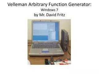
Velleman Arbitrary Function Generator: Windows 7by Mr. David Fritz
You should already have the drivers installed Launch the scope control software. Start > Programs > Velleman > PcLab2000LT
What if the software doesn’t find the scope? • • You may see a pop-up that says you are in Demo mode because the software did not find the scope. • This occasionally happens no matter how often you have used the scope. Click Options > Hardware Setup > PCSGU250 > OK • The software will find the scope and the blue light will illuminate on the front of the scope.
Signal Generator built into the Scope • Generates sine, square, and triangle waveforms, plus other functions. Select the waveform type with the buttons. • Select frequency range with the buttons, then adjust the frequency with the slider • For Amplitude and DC offset, adjust the levels with the sliders or type the values into the boxes.The generator output (here) is set for a 500Hz, 5Vpp sine wave with a 0.98V DC offset - into a high Z load.
Cables • The connections to the Velleman scope are BNC (Bayonet Neill-Concelman) connectors. • You will need to use one BNC cable with either the alligator clips or the IC clips to make your connections between the function generator and your circuit. BNC Connector
Connection • The output of the function generator is the BNC connector closest to the bottom of the Velleman PCSGU250. • The bottom is the heavy side. • When you connect one of your BNC cables, rotate the cable until the nub on the Velleman connector locks in place with the cable. • It takes a slight push in and then twist in the opposite direction to remove the cable from the Velleman PCSGU250.
Your Velleman PCSGU250 is connectedWhat now? • First do a calibration.With no cables connected to the scope, Click Options > Calibrate > OKWait for the Calibration complete pop-up and click OK • Always run a calibration before you begin do anything with the Velleman PCSGU250 if it and/or the computer that is powering it have been off.
Set up the scope’s Arbitrary Function Generator • The Function Generator controls are on the right side of the GUI interface that loads on your computer when you launch PcLab2000LT. • Select the waveform type with the buttons. • Select frequency range with the buttons, then adjust the frequency with the slider • For Amplitude and DC offset, adjust the levels with theslidersor type the values into the boxes.In this case, the generator output is set for a 500Hz, 5Vpp sine wave with a 0.98V DC offset.
DC Output In the pop-up window that opens, select + or – DC, depending on whether you want a voltage output from the function generator that is greater than 0 V or less than 0 V, respectively. Select More Funct.
Setting the amplitude of the DC signal After you click OK, +DC (which is what I selected) will appear in the box below Frequency. To set the amplitude of the DC signal, click in the box labeled Amplitude and type in the value of the DC voltage. It is only allowed to be a number between 0.2 V to 5 V. The position of the line in the graph will change as soon as the function generator begins to output the DC signal with the amplitude that you entered. You do not have to click on Run. Thus, be careful to make sure that the leads for the function generator are connected properly and are not accidentally contacting something that you would rather not drive current through.
Sine wave with a DC offset V(t) = A + Bsin(2πft) f = frequency in Hz A = DC offset voltage (average voltage) B = Sine amplitude Vpp = 2B Vmax = A + B Vmin = A – B 120 VRMS from the AC line has a peak voltage of 170V has a PP voltage of 340V A = 0, B = 170, f = 60
Sinusoidal Output After you click the button with the sine, a plot of a sinusoidal signal will appear in the Output graph. Set the frequency of operation (currently set to 500 Hz) to 1 kHz, which means that you would have to select the 5k range and then either type 1000 in the Frequency box or use the slider labeled Frequency until the value displayed in the box is 1000.0 Hz. Note that the default amplitude is 5.00 Vpp (1.77 VRMS). This is the voltage peak-to-peak. It is not Vm, the amplitude of a 5V sin(wt) sinusoidal signal. It is 2.5V sin(wt). You must set the amplitude to 10Vpp to get a 5V sin(wt) signal out of the function generator.
Connecting the Arbitrary Function Generator After connecting the probe leads to the Generator output, insert wires into the breadboard and clip the probe cable leads to the wires. • Do not attach the clips directly to a resistor. • The heavy probe leads may pull the resistor out of the breadboard • Using wires makes it easier to change the resistor value.
Next? • Make your DC current and voltage measurements using the DMM. • Make your voltage measurements as a function of time using the oscilloscope. • To stop the function generator output, close the PcLab2000LT program.