Download
1 / 35
500 likes | 1.8k Views
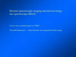
Core loss spectra (EELS, XAS). Kevin Jorissen University of Washington (USA) WIEN2k 2013 Penn State. 1. Concepts. WIEN2k calculates ELNES / XANES. EELS : Electron Energy Loss Spectroscopy XAS: X-ray Absorption Spectroscopy. Ionization edge. EXELFS. ELNES.

E N D
Core loss spectra(EELS, XAS) Kevin Jorissen University of Washington (USA) WIEN2k 2013 Penn State
WIEN2k calculates ELNES / XANES • EELS : Electron Energy Loss Spectroscopy • XAS: X-ray Absorption Spectroscopy Ionization edge EXELFS ELNES Energy Loss
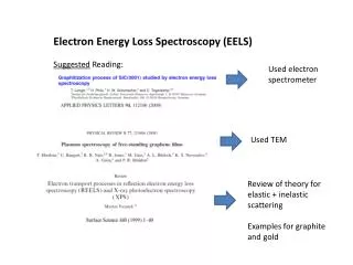
50.0%O-50.0%Mn 66.7%O-33.3%Mn 55.0%O-45.0%Ti 66.7%O-33.3%Ti 66.7%O-33.3%Ti INTRODUCING EELSElectron Energy Loss Spectroscopy is performed in a Transmission Electron Microscope, using a beam of high-energy electrons as a probe. The energy distribution of the beam gives a loss spectrum similar to XAS. Focussed probes give excellent spatial resolution (~0.5 Å). Energy resolution is improving ( ~ 25meV). Electron microscope equipped with EELS-detector Intuitive picture of EELS EELS spectra of TM oxides Probes local electronic structure
Terminology for ionization edges Inner shell ionization.
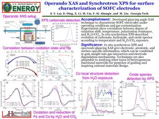
EELS: microscope instrumentation XAS: synchrotron
THEORY OF EELS : A double differential scattering cross-section is calculated by summing over all possible transitions between initial and final states. The transition probabilities are described by Fermi’s golden rule. V is the interaction potential between the fast beam electron and an electron in the sample. F, I the sample states, can be taken from electronic structure calculations. kF and kI the probe states, are typically described as plane waves when Bragg scattering effects are neglected. In experiment, one usually integrates over a range of scattering angles, due to the beam width and spectrometer aperture. differential cross section :
dipole approximation EELS EELS XAS The polarization vector e in XAS plays the same role as momentum transfer q in ELNES within the dipole approximation. This is why people say “XAS = EELS”. (Beware - there are quite a few differences, too.) Probes local, symmetry-selected (lc+1) unoccupied DOS
calculation of spectra using WIEN2k Set up structure and initialize SCF calculation x qtl -telnes Prepare case.innes Prepare case.inxs or x xspec x telnes3 EELS XAS x broadening
w2web ELNES input w2web
Practical considerations • Spectra usually converge easily with respect to RKMAX, k-mesh, SCF criteria • But you should check anyway (see Cu L3) • Optimizing positions may be necessary • You may need to sum over all “C” atoms in the unit cell. (Especially fororientation-resolved calculations.) • You probably need to use a “core hole”. This can be a lot of work. • Your results may be wrong even if you do everything right. (But often theyare reasonably good.) • To compare to experiment, you’ll probably fiddle with the broadening, the onset energy, and the branching ratio (L3/L2)
Features of WIEN2k • Orientation dependence • Beyond dipole selection rule • Several broadening schemes • All-electron For EELS: • Account for collection/convergence angle • Output s(E) or s (q) • Relativistic ELNES ( anisotropic materials)
EELS – Relativistic theory needed for anisotropic materials Semi-relativistic theory : V=|r-r’|-1 m -> g m qE -> qE,rel Fully relativistic theory(P. Schattschneider et al., Phys. Rev. B 2005): Up to leading order in c-2 and using the Lorentz gauge : Geometrical interpretation : in the dipole limit, a relativistic Hamiltonian shrinks the impuls transfer in the direction of propagation. (The general case is more complex.) WIEN2k can also calculate non-dipole relativistic transitions. The equations are so long they make PowerPoint cry.
Beyond the small q approximation The relativistic DDSCS : “Dipole” approximation : More general l,m decomposition :
Relativistic spectra Graphite C K for 3 tilt angles. Beam energy 300 keV, collection angle = 2.4mrad.Left: nonrelativistic calculation. Right: relativistic calculation.
Orientation dependence graphite C K EELS BN B K XAS
Spectrum as a function of energy loss Cr3C2 C K edge
Spectrum as a function of scattering angle Right : the As L3 edge of NiAs (1324 eV) Calculated using WIEN2k+TELNES2 Left: L3 edge of Cr3C2
Just the double-differential CS Double differential scattering cross-section (DDSCS)
Warning! • DFT is a ground state theory ! • it should fail for the prediction of excited state properties • however: for many systems it works pretty well
E E E EF EF EF 2p 2p 2p 2s 2s 2s 1s 1s 1s ELECTRON MICROSCOPY FOR MATERIALS RESEARCH The core hole
Different ways of treating the core hole within WIEN2k • No core hole (= ground state, sudden approximation) • Z+1 approximation (eg., replace C by N) • Remove 1 core electron, add 1 electron to conduction band • Remove 1 core electron, add 1 electron as uniform background charge • Fractional core hole: remove between 0 and 1 electron charge (e.g. 0.5) • You may still get a bad result – correct treatment requires a more advanced theory, e.g. BSE treats electron-hole interaction explicitly (gold standard). Core hole calculations usually require a supercell !!!
Mg-K in MgO • mismatch between experiment and simulation • introduction of core hole or Z+1 approximation does not help • interaction between neighbouring core holes • core hole in a supercell C. Hébert, J. Luitz, P. Schattschneider Micron 34, 219 (2003)
Challenges of WIEN2k • 1. Basis set only meant for limited energy range : • forget about EXAFS/EXELFS • sometimes adding a LO (case.in1) with a high linearization energy of 2.0 or 3.0improves description of high-energy states. • 2. Sometimes Final State Rule (core hole) DFT just isn’t good enough and you need Bethe-Salpeter (BSE) calculations • codes : OCEAN, AI2NBSE, Exc!ting, “BSE” • much more expensive • not as “polished” as DFT • gets L3/L2 ratios right reality BSE single-particle
Challenges of WIEN2k • 3. Core hole supercell size can be hard to converge. • size of the cell • how much charge to remove? • optimal treatment can differ between similar materials; or even different edges in same material above: diamond GaN N K edge S. Lazar, C. Hébert, H. W. Zandbergen Ultramicroscopy 98, 2-4, 249 (2004)
Challenges of WIEN2k 4. Killing artifacts (unphysical monopoles) by “extending the RMT”
Documentation • WIEN2k Users Guide! • C. Hebert, Practical aspects of calculating EELS using the WIEN2k code, Ultramicroscopy, 2007 • Jorissen, Hebert & Luitz, submitting (http://leonardo.phys.washington.edu/feff/papers/dissertations/thesis_jorissen.pdf - Kevin’s Ph.D. thesis)
3. Hands-on exercises 1. XAS of K edge of Cu. 2. averaged EELS of N K edge of GaN. 3. orientation sensitive, in-plane and out-of-plane EELS of N K edge of GaN. 4. core hole calculation for Cu K-edge XAS & compare. 5. initialize a 2*2*2 supercell for TiC or TiN core hole EELS calculation. 6. Be K edge. Find the error.
Thank you: • C. Hebert, J. Luitz, P. Schattschneider, and the TELNES team • P. Blaha, K. Schwarz, and the WIEN2k team • J. Rehr and the FEFF9 team • WIEN2013 organizers