Download
1 / 42
760 likes | 2k Views
Flixborough Explosion. Flixborough Explosion 1 st June 1974 28 Workers killed when an explosion occurred in a plant processing Cyclohexane Thanks to Ann-Marie McSweeney &John Barrett Department of Process Engineering, UCC. Flixborough Explosion. Accident Overview

E N D
Flixborough Explosion Flixborough Explosion 1st June 1974 28 Workers killed when an explosion occurred in a plant processing Cyclohexane Thanks to Ann-Marie McSweeney &John Barrett Department of Process Engineering, UCC
Flixborough Explosion Accident Overview • A temporary pipe was fitted between two sequential reactors in a plant that was oxidising cyclohexane at elevated temperature and pressure. • The pipe was not designed properly and the mechanical loads acting on the pipe were not correctly identified. • In particular the pipe was subject to large bending loads for which it had not been designed. • The pipe broke open at a thermal expansion bellows fitting in the line. • Large amounts of liquid cyclohexane escaped through the ruptured pipe and vapourised. • The vapour cloud found an ignition source and a fireball ensued.
Flixborough Explosion Flixborough Explosion A very good description of the incident is given in the book MAJOR CHEMICAL HAZARDS AUTHOR: V.C. MARSHALL (In the UCC Library under Classification 660.28) Also the Report of the Court of Enquiry. The course notes for PE 2002 should also be consulted especially the material dealing with bending of beams and loading of pressure vessels.
Flixborough Explosion View of the Scene after the Incident
Flixborough Explosion View of the Scene after the Incident
Flixborough Explosion View of the Scene after the Incident
Flixborough Explosion PRODUCT DESCRIPTION Raw material was cyclohexane (basically the alkane hexane with its ends joined up!) Formula C6H12 Molecular Weight M = 84 Boiling Point at Patm = 81 °C i.e. Cyclohexane is a volatile liquid with a low boiling point at ambient conditions (something like petrol!) Liquid Density 780 kg/m3 Vapour Density (at Patm) 2.4 kg/m3 Hence the liquid is lighter than water while the vapour is heavier than air (in common with many hydrocarbons).
Flixborough Explosion PRODUCT DESCRIPTION Cyclohexane has the following thermodynamic properties Specific Heat Capacity Cp = 1.93 kJ/kgK Ratio of Specific Heats = Cp/Cv = 1.087 Latent heat of evaporation λ = 360 kJ/kg Flammability (in air) of the gas 5.3 % to 8.3 %
Flixborough Explosion PROCESS DESCRIPTION & REACTOR CONFIGURATION The Flixborough petrochemical plant was involved in the production of cyclohexanone, a precursor for the manufacture of Nylon. The raw material cyclohexane was oxidised to cyclohexanone by injecting air in the presence of a catalyst. The process of oxidation is slow and it was decided to use six stirred reactors in series with the product from the first overflowing into the second and so on. To do this the reactors were mounted on a platform arranged in a series of steps each 0.355 m higher than the one following. Good reaction kinetics dictated that the cyclohexane in the reactors be maintained at the elevated temperature of 155 °C. This temperature is above its boiling point at atmospheric pressure so to hold it a liquid state, the reactors had to be operated at 9 bar pressure.
Flixborough Explosion Oxidation of Cyclohexane
Flixborough Explosion REACTOR CONFIGURATION
Flixborough Explosion REACTOR CONFIGURATION This schematic view indicates the basis of the incident.
Flixborough Explosion PROCESS DESIGN FLAW The cyclohexane in the reactors was in a liquid state at a temperature 74 °C above its atmospheric pressure boiling point. Hence any loss of containment would produce large scale flashing and escape of flammable vapour! In other words if any part of the reactor wall or associated piping broke, the pressure would suddenly fall from 9 bar to 1 bar (atmospheric pressure) and a huge amount of cyclohexane vapour would be generated. Calculate of the proportion of liquid cyclohexane that would vapourise (flash off). Considering an adiabatic energy balance: – energy consumed in evaporating off vapour is provided by cooling of the liquid fraction from 155 °C down to 81 °C.
Flixborough Explosion PROCESS DESIGN FLAW Fraction Evaporated About 40 % of the cyclohexane will vapourize. Given the inventory of cyclohexane in the reactor train was about 100 tonnes, thus in the event of an accident, 40 tonnes of vapour would be released. Being heavier than air, cyclohexane if released would form a cloud in the shape of an up-turned bowl. At the centre of the cloud, the vapour would be close to pure cyclohexane but at the fringes, where it is mixed with air, the concentration could lie in the flammable range.
Flixborough Explosion CONTAINMENT DESCRIPTION An unwanted by-product of the oxidation reaction were some very corrosive acids, which could only be contained by stainless steel. However stainless can be 10 times the price of mild steel so the solution was to make the reactors out of 12.5 mm thick mild steel with the reactor insides lined with 3 mm thick stainless steel The reactors were vertical cylindrical vessels with a diameter of approximately 3 m and height of 6 m. The outsides were lagged with thermal insulation protected by aluminium cladding. Each reactor was adjoined to the adjacent reactors by a short stub pipe of 0.7 m diameter. Due to the close proximity of the reactors to each other, the length of this stub pipe was only about 1.5 m There were a number of pressure relief valves in the system set to lift at 11 bar.
Flixborough Explosion INCIDENT DESCRIPTION Sometime in March 1974, cooling water was sprayed on the outside of Reactor 5 to quench a minor leak from a valve. However the water was contaminated with chemicals which corroded the mild steel casing of the reactor. The fact that the steel shell was under a tensile hoop stress due to the contained pressure would have accelerated the damage (a phenomenon known as stress corrosion). This corrosion had the result that more of the mechanical load was transferred to the stainless steel liner which was then overstressed and it in turn cracked. Cyclohexane vapour began to leak from the reactor. A first lesson of this would be that the system could leak as a result of external corrosion (presumably not considered due to the lagging).
Flixborough Explosion INCIDENT DESCRIPTION This reactor had to be shutdown and removed from service for repair. To keep the process running, it was decided to fabricate a temporary by-pass pipe to join Reactor Number 4 to Reactor Number 6. POOR MECHANICAL DESIGN OF THE BY-PASS PIPE WAS THE REASON FOR THE DISASTER
Flixborough Explosion BY-PASS PIPE GEOMETRY The pipe in question (i.e. the by-pass) formed a connection between two adjacent reactors over 6 metres apart. The reactor nozzles were vertically off-set for process flow considerations so the pipe had to have a dog-leg bend in it. The end of the pipe connecting to Reactor Number 4 was at a higher elevation (0.35 m) than the end connecting to Reactor Number 6. The by-pass pipe itself had a bore of 0.5 m though the stub pipes emanating from both reactors were of a larger diameter of 0.7 m. There were two bellows in the stub pipes to permit axial expansion or contraction of the pipework. The by-pass pipe was fabricated from stainless steel.
Flixborough Explosion By-Pass Pipe Geometry
Flixborough Explosion By-Pass Pipe Geometry
Flixborough Explosion Mechanical Properties The mechanical properties of the by-pass pipe material would be expected to be Young’s Modulus E = 200 GPa Coefficient of thermal expansion Tensile Strength Steel Density
Flixborough Explosion Membrane Stress in Pipe Wall due to Fluid Pressure Because the pipe between the two reactors contains a pressurized fluid, stresses will be developed in its walls. The hoop (circumferential) stress will be: Fluid Pressure P = 9 bar Pipe Diameter D = 0.5 m Pipe wall thickness t = 0.006 mm (In fact this is a guess; 6 mm is ¼ inch) This is certainly an acceptable stress level.
Flixborough Explosion Membrane Stress in Pipe Wall due to Fluid Pressure Also have longitudinal stress in the pipe wall These were the only stress calculations carried out! There was (and is) a piping design code which requires more rigorous calculations and tests to be carried out on new piping. However (unlike vessels) compliance with the code is not legally binding.
Flixborough Explosion BY-PASS PIPE BELLOWS REQUIREMENT There were two austenitic stainless steel bellows at each end of the by-pass where it joined the stub pipes (nozzles) from the reactors. This was the fundamental fault with the arrangement yet they were essential. The need to have a bellows in the pipe can be reviewed. At times of plant shutdown, the pipe will be at ambient temperature Tamb; say 15 °C. During plant operation, pipe temperature will rise to the operating temperature of 155 °C.
Flixborough Explosion BELLOWS REQUIREMENT For a straight pipe with no bellows and assuming the reactor vessels at either end act as perfectly rigid restraints, the induced thermal stress, T assuming there is no accommodation of thermal expansion will be This is a compressive stress and is of such a magnitude as to certainly cause damage to the pipe.
Flixborough Explosion BELLOWS REQUIREMENT To avoid any thermal stress, the bellows must allow free axial thermal expansion of an amount Note: A bellows is a flexible pipe section that allows large axial deflection without generating high axial loads. Because of their construction a bellows cannot tolerate any significant non-axial loads. In the original system configuration where adjacent reactors were joined by short straight lengths of piping, all the main pipe loads were axial. This was not the case for the dog-leg by-pass pipe, a fact not taken into account at the time.
Flixborough Explosion Bellows Joint Illustration The picture shows a pipe section with a bellows at either end (i.e. the hoops)
Flixborough Explosion BY-PASS PIPE LOAD ANALYSIS In addition to the membrane stresses in the wall of the pipe due to fluid internal pressure, there are two additional mechanical loads. Weight Loading The normal span of the pipe running between adjacent reactors was something over 1 m. However between Reactors 4 and 6 a span of 6.5 m was present. Thus bending due to weight loading (sagging) may be significant. The weight of pipe wall and of product inside the pipe can be found by calculating the volume of each component and multiplying it by the respective density:
Flixborough Explosion BY-PASS PIPE WEIGHT LOADING ANALYSIS Pipe inside diameter Di = 0.5 m Pipe outside diameter Do = 0.5 + 2 x 0.006 =0.512m Pipe length L = 6.5 m Steel density s = 7800 kg/m3 Cyclohexane density p = 780 kg/m3
Flixborough Explosion Bending Moment due to Non-Collinear Fluid Pressure Forces The dog-leg bend in the pipe means that a moment is developed due to the equal, opposite, parallel and non-collinear fluid pressure forces that the pipe is subject to at either end. The Bending Moment due to the pressure forces, Mp is e – pipe offset (or eccentricity) = 0.4 m The pressure forces, Fp are:
Flixborough Explosion Bending Moment In By-Pass Pipe Note the diameter of 0.7 m is taken because fluid pressure is developed at the original stub pipes. This was not included in stress calculations carried out on the by-pass and is of critical importance!This Bending Moment by far the larger of the two loads.
Flixborough Explosion Beam Analysis of By-Pass Pipe Having identified the loads, the response of the by-pass pipe to them can be studied. The actual by-pass pipe support was quite complicated with the arrangement being supported by scaffolding poles. Also because of the two dog-leg (mitre) joints, the cross section is not constant. Treat the pipe/reactor flange and adjacent bellows as a simple support • Provides resistance to deflection. • Provides no resistance to slope (because of the bellows). Treat the by-pass pipe as a straight beam.
Flixborough Explosion Beam Analysis of By-Pass Pipe So the structure corresponds to a simply supported beam subject to a uniformly distributed weight load and a moment at the centre of the span. The magnitude of the uniformly distributed load, q is The magnitude of the applied bending moment, Mp is
Flixborough Explosion Beam Analysis of By-Pass Pipe A Shear Force and Bending Moment diagram for the beam can be drawn.Firstly must calculate the reaction forces at either end of the beam, RA and RB respectively by considering equilibrium of the structure. Equilibrium of Vertical Forces Equilibrium of Moments about end A The reaction force is largest at support B i.e. at the bellows attached to reactor number 6. At this end, the load due to supported weight and the bending moment sum together. Note that the reaction force at support A is
Flixborough Explosion Shear Force & Bending Moment Diagram for Pipe
Flixborough Explosion PIPE RUPTURE The above calculations indicate that the bellows at the lower end of the pipe (adjacent to Reactor Number 6) was exposed to a non-axial (in fact a perpendicular or transverse) force of almost 30 kN. This would have been sufficient to rupture the bellows and allow large quantities of cyclohexane to leak out. This was agreed as being the probable cause of failure. What is known is that on the date in question, this by-pass pipe running between reactors Numbers 4 and 6, ruptured and released in the region of 40 tonnes of cyclohexane vapour. The cloud subsequently ignited probably due to contact with open flames in an adjacent Hydrogen plant and exploded.
Flixborough Explosion FIRE BALL (BLEVE) CALCULATIONS Model the instantaneous combustion of the escaped vapour. Duration of burning of fire ball is The radiative power of the fire can be calculated from QR Radiative powerW HC Calorific Value J/kg td Duration of fire ball s M Mass of fuel in fire ball kg
Flixborough Explosion FIRE BALL (BLEVE) CALCULATIONS A point source model of the fire gives the radiative heat flux as Radiative flux W/m2 QR Radiative power of flame W r Distance from source m In turn the thermal radiation dosage can be calculated as L Thermal radiation dosage (kW/m2)1.33s Intensity of radiation (radiation flux) kW/m2 t Duration of exposure s
Flixborough Explosion FIRE BALL (BLEVE) CALCULATIONS Note the duration of exposure is equal to the duration of the fire ball. Damage to people exposed to the fire can be quantified with Hence can estimate how close people must have been to the fire to have been killed or injured.
Flixborough Explosion EXPLOSION AFTERMATH Picture shows reactors 4 and 6 after the accident.
Flixborough Explosion EXPLOSION AFTERMATH Picture shows the by-pass pipe after the accident
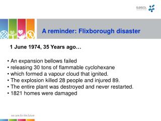
Flixborough Explosion CONCLUSIONS • 28 workers were killed and 36 injured on the site. • 53 people were injured off-site. • 1821 houses were damaged. Lessons The accident occurred due to: • Poor Process Design • Lack of Understanding of Mechanical Loading of Process Equipment