Download
1 / 1
10 likes | 107 Views
This demonstration site showcases a ground source heat pump system retrofit in a university building used by the Faculty of Visual Arts. The building's features, specifications, and energy performance are detailed. The heating and cooling system utilizes a heat pump prototype by OCHSNER Wärmepumpen GmbH, providing both heating and active cooling capabilities. The system includes a borehole heat exchanger, radiant walls, and an intricate hydraulic layout for each function. The energy efficiency and performance data of the heat pump are highlighted, indicating a high coefficient of performance. The building also incorporates monitoring systems for energy consumption and thermal energy measurement. Overall, this project demonstrates sustainable and effective use of renewable energy for indoor climate control.

E N D
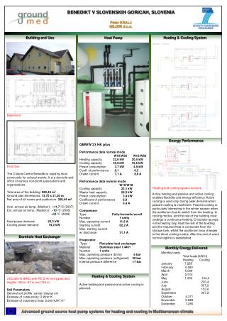
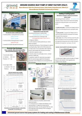
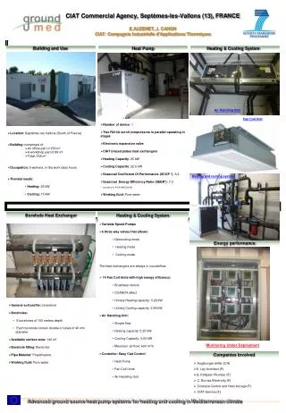
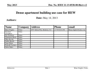
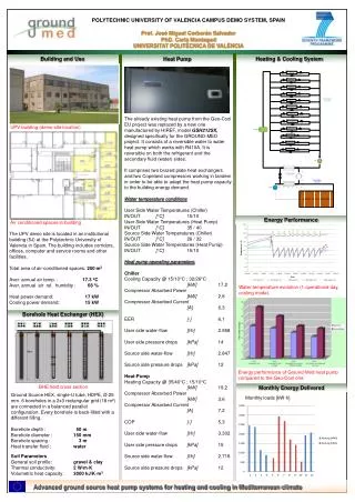
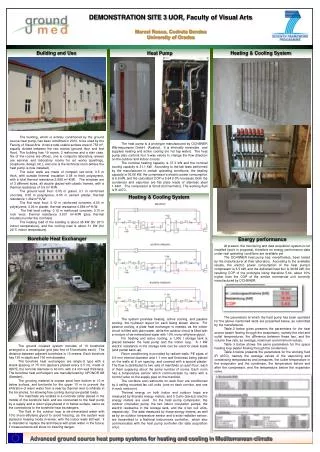
DEMONSTRATION SITE 3 UOR, Faculty of Visual Arts Marcel Rosca, Codruta Bendea University of Oradea Building and Use Heating & Cooling System Heat Pump The building, which is entirely conditioned by the ground source heat pump, has been retrofitted in 2010, to be used by the Faculty of Visual Arts. It has a total usable surface area of 753 m2, equally divided between the two stories (ground floor and first floor). The building has 19 rooms, 2 restrooms and a stair case. Six of the rooms are offices, one is computer laboratory, eleven are seminar and laboratory rooms for art works (paintings, sculptures, design etc.), and one is the technical room (where the heat pump is now installed). The outer walls are made of compact red brick, 0.5 m thick, with outside thermal insulation 0.08 m thick polystyrene, with a total thermal resistance 2.668 m2·K/W. The windows are of 3 different sizes, all double glazed with plastic frames, with a thermal resistance of 0.5 m2·K/W. The ground level floor: 0.05 m gravel, 0.1 m reinforced concrete, 0.05 m polystyrene, 0.05 m cement plaster, thermal resistance 1.382 m2·K/W. The first level floor: 0.12 m reinforced concrete, 0.03 m polystyrene, 0.05 m plaster, thermal resistance 0.884 m2·K/W. The first level ceiling: 0.12 m reinforced concrete, 0.15 m rock wool, thermal resistance 3.831 m2·K/W (plus thermal insulation under the roof tiles). The heating load of the building is about 38 kW (for 20°C indoor temperature), and the cooling load is about 31 kW (for 24°C indoor temperature). The heat pump is a prototype manufactured by OCHSNER Wärmepumpen GmbH(Austria). It is internally reversible and supplies heating and active cooling (no hot tap water). The heat pump also controls four 3-way valves to change the flow direction on the outdoor and indoor circuits. The nominal heating capacity is 37.3 kW and the nominal cooling capacity is 31.1 kW. According to the lab tests performed by the manufacturer in certain operating conditions, the heating capacity is 36.66 kW, the compressor’s electric power consumption is 6.5 kW, and the calculated COP is 5.64 (10% increase). Both the condenser and vaporizer are flat plate made of stainless steel 1.4401. The compressor is Scroll (full hermetic). The working fluid is R 407C. Heating & Cooling System Borehole Heat Exchanger Energy performance At present, the monitoring and data acquisition system is not installed (work in progress), therefore no energy performance data under real operating conditions are available yet. The OCHSNER heat pump has, nevertheless, been tested by the manufacturer at their laboratory. According to the available results, the electric power consumption of the heat pump’s compressor is 6.5 kW, and the delivered heat flux is 36.66 kW, the resulting COP of the prototype being therefore 5.64, about 10% higher than the COP of the similar commercial unit currently manufactured by OCHSNER. The parameters at which the heat pump has been operated for the above mentioned tests are presented below, as submitted by the manufacturer. Table 2 below gives presents the parameters for the heat source (water flowing through the evaporator), namely the inlet and outlet temperatures, the difference between these two, and the volume flow rate, as average, maximum and minimum values. Table 3 below shows the same parameters for the space heating loop (water flowing through the condenser). Table 4 below presents the parameters for the working fluid (R 407C), namely the average values of the vaporizing and condensing temperatures and pressures, the outlet temperature in the evaporator and the condenser, the temperature before and after the compressor, and the temperature before the expansion valve. The system provides heating, active cooling, and passive cooling, the hydraulic layout for each being shown above. For passive cooling, a plate heat exchanger is needed, as the indoor circuit is filled with plain water, while the outdoor circuit is filled with a mixture of de-mineralized water with 10% mono-ethylene glycol. For heating and active cooling, a 1,000 l storage tank is placed between the heat pump and the indoor loop. A 7 kW electric resistance in the storage tank can be used for peak loads (and partial back-up). Room conditioning is provided by radiant walls, PE pipes of 9.9 mm internal diameter and 1.1 mm wall thickness being placed on the walls at 8 cm spacing, and covered with a special plaster. The flow is distributed to two sets of manifolds on each floor, each of them supplying about the same number of rooms. Each room has a temperature sensor which communicates by radio with a control valve on the supply pipe on the manifold. The corridors and restrooms on each floor are conditioned by 4 ceiling mounted fan coil units (one on each corridor, and one in each restroom). Thermal energy on both indoor and outdoor loops are measured by Brunata energy meters, and 5 Carlo Gavazzi electric energy meters are used for the heat pump compressor, the outdoor circulation pump, the two indoor circulation pumps, the electric resistance in the storage tank, and the 4 fan coil units, respectively. The data measured by these energy meters, as well as by an outdoor temperature sensor and a solar radiation sensor, are transmitted to a National Instruments controller, which also communicates with the heat pump controller (for data acquisition only). The ground coupled system consists of 10 boreholes arranged in a rectangular grid (two line of 5 boreholes each). The distance between adjacent boreholes is 10 meters. Each borehole has 130 m depth and 150 mm diameter. The borehole heat exchangers are single-U type with a shank spacing of 75 mm (spacers placed every 2.5 m), made of HDPE, the nominal diameter is 40 mm, with 2.4 mm wall thickness. The borehole heat exchangers are manufactured by UPONOR AB (Sweden). The grouting material is coarse sand from bottom to 10 m below surface, and bentonite for the upper 10 m to prevent the infiltration of warm water from a near-by thermal river to infiltrate in the boreholes, for allowing free cooling during low partial loads. The manifolds are located in a concrete cellar placed in the middle of the borehole field, and are connected to the heat pump by a supply and a return pipe placed 2 m below surface, same as the connections to the borehole heat exchangers. The fluid in the outdoor loop is de-mineralized water with 10% mono-ethylene glycol to avoid freezing, as the system was started in heating mode in winter, with the indoor walls still wet. It is intended to replace the anti-freeze with plain water in the future, if measurements will show no freezing danger.