68HC11 Demo Program Lab for 68HC11 Microcontroller
Learn how to communicate with a 68HC11 microcontroller from a PC, run a demo program, and make LED lights blink. Follow step-by-step instructions in this lab using the 68HC11 and MicroStamp11 devices.

68HC11 Demo Program Lab for 68HC11 Microcontroller
E N D
Presentation Transcript
68HC11 Demo Program This is our first lab using the 68HC11 microcontroller. We will “talk” to the microcontroller from a PC, run a demo program, and cause LED lights to blink. You microcontroller may have been reprogrammed by students last year. If that is the case, you will need to reload the demo program from disk to the microcontroller.
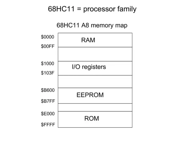
Overview of the Lab • The 68HC11 comes loaded with a demo program in EEPROM, that we will play with in the lab. • EEPROM is Electrically Erasable Programmable Read-Only Memory. • The demo program allows the user to communicate with the 68HC11 from a terminal program on the PC, over a serial connection. • The demo program allows the user to toggle (reverse) three bits of one of the output ports (port A). • We will connect those three bits of port A to LEDs on the IDL-800 Digital Lab • We will verify operation of the board and demo program.
Part A, powering the MicroStamp11 • The MicroStamp11 has a demo program already programmed into the EEPROM when you receive it. This is a useful program for testing your communications setup and monitoring and controlling the various I/0 lines of the micro. • Plug the MicroStamp11 into the Docking Module (may already be plugged in), and supply power via the external power connector. (See diagram on the next page.) • Connect a DC voltage greater than 5.6 Volts to the external power connector (J1) on the Docking Module. Red is positive, and black is negative (ground). CAUTION! Make sure you have the polarity correct! • Turn on the IDL-800. The LED on the MicroStamp11 should blink twice. Notify your instructor if it does not, and complete part A2. • Turn off the IDL-800 power.
Power Communication to PC Output Reset
Power LED (Yellow) D2 LED (RED)
Note: Correct Switch Positions to run the demo program SW2: RUN BOOT SW3: WRITE PROT
PART A-2 Downloading the Demo Program • Complete this set of steps if your microcontroller does not run the demo program on boot-up. • Connect the serial cable between the Docking Module and a serial port on your PC. (With some PCs, you will need a 9-pin to 25-pin adapter.) • Obtain a 68HC11 Utilities floppy disk. • Insert the floppy disk, and open a DOS window. • Change to the A: drive, and to a subdirectory called mstamp11. • At the DOS prompt, • type PMS1 MS11DEMO • Follow the instructions on the screen. To Set the RUN/BOOT switch (SW2) to boot, and the WRITE/PROT switch (SW3) to write, see the previous slide.
Part B: The Terminal Connection to the 68HC11 • To use the demo program, connect the supplied serial cable between the Docking Module and a serial port on your PC. (With some PCs, you will need a 9-pin to 25-pin adapter.) • Run the WindowsTerminal program (HyperTerminal, under Accessories) on your PC. • Configure your terminal program: • set the baud rate to 9600 • parity to NONE • # DATA BITS = 8 • #STOP BITS = 1. • Ensure that SW2 is set to RUN. (see diagram next page) • Power on the IDL-800. • Press the Docking Module RESET button. LED DI will blink twice, indicating the demo programming is running. • Press <ENTER> on your keyboard. • A menu of commands will appear on your terminal window's screen, followed by a command prompt '?‘ symbol. • Each command is activated by a single keystroke. • A sample screen showing results of each command is shown in the following page.
Part C: The Demo Program Typing a command not listed will cause the menu to be re-displayed. The A and D commands in the demo program allow you to examine the states of PORTA and PORTD. We will work with PORTA. C – will clear the upper 5 bits of PORTA (leaving a binary 3) A – will display the bits of PORTA as a decimal number. We have to convert the number to binary to see what bits are set. 4,5,6 – will toggle bits 4,5, or 6 respectively. • Enter A to see the state of PORTA. • Enter C to clear PORTA. • Enter A to see the state of PORTA. • Enter 4 to toggle bit 4 or PORTA. • Enter A to see the state of PORTA. • Confirm that the correct bit was set, by converting PORTA to a binary number.
Part D: Wiring the MicroStamp11 to LEDs • Turn OFF the IDL-800. • Locate pins 4,5, and 6 on the MicroStamp docking module. • Connect a wire from each pin to the appropriate LED light on the IDL-800. • Turn on the IDL-800. • Clear PORTA. • Toggle Bit-4. Observe the LED. • Display PORTA. Correct binary value? • Toggle Bit-5. Observe the LED. • Display PORTA. Correct binary value? • Toggle Bit-6. Observe the LED. • Display PORTA. Correct binary value? • Turn OFF the IDL-800
Speaker Output Read Only: we do not have a speaker available. In the demo program, PA6 is used as a tone output for a speaker. It is also connected to LED DI, when plugged into the Docking Module, to provide a visual output. You can drive a small piezo speaker directly by hooking one end to PA6 through a 330-Ohm resistor, and the other end to ground. When you press RESET, or type 'S‘ when the demo program is running, you will hear two beeps from the speaker.