CIRCUIT REPRESENTATIONS
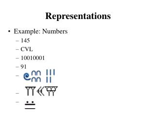
CIRCUIT REPRESENTATIONS. Boolean Functions. Boolean algebra deals with binary variables and logic operations. Function results in binary 0 or 1. x 0 0 0 0 1 1 1 1. y 0 0 1 1 0 0 1 1. z 0 1 0 1 0 1 0 1. F 0 0 0 0 1 0 1 1. x. y. F = x(y+z’). z. y+z’. z’.


CIRCUIT REPRESENTATIONS
E N D
Presentation Transcript
Boolean Functions Boolean algebra deals with binary variables and logic operations. Function results in binary 0 or 1 x 0 0 0 0 1 1 1 1 y 0 0 1 1 0 0 1 1 z 0 1 0 1 0 1 0 1 F 0 0 0 0 1 0 1 1 x y F = x(y+z’) z y+z’ z’ F = x(y+z’)
Boolean Functions G 0 0 0 1 0 0 1 1 x xy y G = xy +yz z yz x 0 0 0 0 1 1 1 1 y 0 0 1 1 0 0 1 1 z 0 1 0 1 0 1 0 1 xy 0 0 0 0 0 0 1 1 yz 0 0 0 1 0 0 0 1 We will learn how to transition between equation, symbols, and truth table.
Representation Conversion Need to transition between boolean expression, truth table, and circuit (symbols). Boolean Expression Circuit Truth Table
Truth Table to Expression Converting a truth table to an expression Each row with output of 1 becomes a product term Sum product terms together. G 0 0 0 1 0 0 1 1 x 0 0 0 0 1 1 1 1 y 0 0 1 1 0 0 1 1 z 0 1 0 1 0 1 0 1 Any Boolean Expression can be represented in sum of products form! xyz + xyz’ + x’yz
Equivalent Representations of Circuits All three formats are equivalent Number of 1’s in truth table output column equals AND terms for Sum-of-Products (SOP) x x x x 0 0 0 0 1 1 1 1 y 0 0 1 1 0 0 1 1 z 0 1 0 1 0 1 0 1 G 0 0 0 1 0 0 1 1 G x x x x x x x z y G = xyz + xyz’ + x’yz
Reducing Boolean Expressions Is this the smallest possible implementation of this expression? No! Use Boolean Algebra rules to reduce complexity while preserving functionality. Step 1: Use Theorem 1 (a + a = a) So xyz + xyz’ + x’yz = xyz + xyz + xyz’ + x’yz Step 2: Use distributive rule a(b + c) = ab + ac So xyz + xyz + xyz’ + x’yz = xy(z + z’) + yz(x + x’) Step 3: Use Postulate 3 (a + a’ = 1) So xy(z + z’) + yz(x + x’) = xy · 1 + yz · 1 Step 4: Use Postulate 2 (a · 1 = a) So xy · 1 + yz · 1 = xy + yz = xyz + xyz’ + x’yz G = xyz + xyz’ + x’yz
Minterms and Maxterms Each variable in a Boolean expression is a literal Boolean variables can appear in normal (x) or complement form (x’) Each AND combination of terms is a minterm Each OR combination of terms is a maxterm For example: Minterms x y z Minterm 0 0 0 x’y’z’ m0 0 0 1 x’y’z m1 … 1 0 0 xy’z’ m4 … 1 1 1 xyz m7 For example: Maxterms x y z Maxterm 0 0 0 x+y+z M0 0 0 1 x+y+z’ M1 … 1 0 0 x’+y+z M4 … 1 1 1 x’+y’+z’ M7
Representing Functions with Minterms Minterm number same as row position in truth table (starting from top from 0) Shorthand way to represent functions x 0 0 0 0 1 1 1 1 y 0 0 1 1 0 0 1 1 z 0 1 0 1 0 1 0 1 G 0 0 0 1 0 0 1 1 G = xyz + xyz’ + x’yz G = m7 + m6 + m3 = Σ(3, 6, 7)
Complementing Functions Minterm number same as row position in truth table (starting from top from 0) Shorthand way to represent functions G 0 0 0 1 0 0 1 1 G’ 1 1 1 0 1 1 0 0 x 0 0 0 0 1 1 1 1 y 0 0 1 1 0 0 1 1 z 0 1 0 1 0 1 0 1 G = xyz + xyz’ + x’yz G’ = (xyz + xyz’ + x’yz)’ = Can we find a simpler representation?
Complementing Functions Step 1: assign temporary names b+ c-> z (a+ z)’ = G’ Step 2: Use DeMorgans’ Law (a+ z)’ = a’ · z’ Step 3: Resubstitute (b+c) for z a’ · z’ = a’ · (b + c)’ Step 4: Use DeMorgans’ Law a’ · (b + c)’ = a’ · (b’ · c’) Step 5: Associative rule a’ · (b’ · c’) = a’ · b’ · c’ G = a + b+ c G = a + b+ c G’ = (a + b+ c)’ G’ = a’ · b’ · c’ = a’b’c’
Complementation Example Find complement of F = x’z + yz F’ = (x’z + yz)’ DeMorgan’s F’ = (x’z)’ (yz)’ DeMorgan’s F’ = (x’’+z’)(y’+z’) Reduction -> eliminate double negation on x F’ = (x+z’)(y’+z’) This format is called product of sums
Conversion Between Canonical Forms Easy to convert between minterm and maxterm representations For maxterm representation, select rows with 0’s x 0 0 0 0 1 1 1 1 y 0 0 1 1 0 0 1 1 z 0 1 0 1 0 1 0 1 G 0 0 0 1 0 0 1 1 G = xyz + xyz’ + x’yz G = m7 + m6 + m3 = Σ(3, 6, 7) G = M0M1M2M4M5 = Π(0,1,2,4,5) G = (x+y+z)(x+y+z’)(x+y’+z)(x’+y+z)(x’+y+z’)
Representation of Circuits All logic expressions can be represented in 2-level format Circuits can be reduced to minimal 2-level representation Sum of products representation most common in industry.
Why do we need HDLs ? HDL can describe both circuit structure and behavior Schematics describe only circuit structure C language describes only behaviors Provide high level abstraction to speed up design High portability and readability Enable rapid prototyping Support different hardware styles 16
Verilog Overview A Hardware Description Language (HDL) for describing & testing logic circuits. text based way to talk about designs easier to simulate before silicon translate into silicon directly Logic synthesis - automatic generation of lower-level logic circuit designs from high-level specifications
Why Verilog? Verilog: Similar to C, with some changes to account for time Widely used in industry VHDL is alternative; similar and can pick it up easily. Verilog simpler to learn! We employ only a simple subset of Verilog.
Verilog Overview Verilog is only a hardware description language Although it looks like a general purpose language Describing circuits is not equivalent to programming Need to figure out the circuit first and then how to use Verilog to describe it.
Verilog Overview Verilog description composed of modules: moduleName ( port list ) ; Declarations and Statements; Endmodule Modules can have instantiations of other modules, or use primitives supplied by language
Verilog Overview Verilog has 2 basic modes 1. Structural composition: describes the structure of the hardware components, including how ports of modules are connected together module contents are builtin gates (and, or, xor, not, nand, nor, xnor, buf) or other modules previously declared 2. Behavoral: describes what should be done in a module module contents are C-like assignment statements, loops
Example: Structural XOR module xor(X, Y, Z); input X, Y; output Z; wire notX, notY, XnotY, YnotX; not (notX, X), (notY, Y); and (YnotX, notX, Y), (XnotY, X, notY); or (Z, YnotX, XnotY); endmodule X Y Z X Y notX YnotX XnotY notY
Example: Structural XOR module xor(X, Y, Z); input X, Y; output Z; wire notX, notY, XnotY, YnotX; not (notX, X), (notY, Y); and (YnotX, notX, Y), (XnotY, X, notY); or (Z, YnotX, XnotY); endmodule X Y Z X Y which “ports” input, output Default is 1 bit wide data “ports” connect components notX YnotX XnotY notY Note: order of gates doesn’t matter, since structure determines relationship
Example: Behavoral XOR in Verilog module xorB(X, Y, Z); input X, Y; output Z; reg Z; always @ (X or Y) Z = X ^ Y; endmodule Unusual parts of above Verilog “always @ (X or Y)” => whenever X or Y changes, do the following statement “reg” is only type of behavioral data that can be changed in assignment, so must redeclare Z Default is single bit data types: X, Y, Z
Verilog: replication, hierarchy Often in hardware need many copies of an item, connected together in a regular way Need way to name each copy Need way to specify how many copies Specify a module with 4 XORs using existing module example
Example: Replicated XOR in Verilog module 4xor(A, B, C); input[3:0] A, B; output[3:0] C; xorB My4XOR[3:0] (.X(A), .Y(B), .Z(C) ); endmodule Note 1: can associate ports explicitly by name, (.X (A), .Y(B), .Z(C) ) or implicitly by order (as in C) (A, B, C) Note 2: must give a name tonew instance of xors (My4XOR) A[2] A[3] A[0] A[1] B[0] B[1] B[2] B[3] C[3] C[0] C[1] C[2] A[1] A[0] A[2] A[3] B[3] B[1] B[2] B[0]
Verilog big idea: Time Difference from normal prog. lang. is that time is part of the language part of what trying to describe is when things occur, or how long things will take In both structural and behavoral Verilog, determine time with #n : event will take place in n time units structural: not #2(notX, X) says notX does not change until time advances 2 ns behavoral: Z = #2 A ^ B; says Z does not change until time advances 2 ns Default unit is nanoseconds; can change
Example: “Initial” means do this code once Note: Verilog uses begin … end vs. { … } as in C #2 stream = 1 means wait 2 ns before changing stream to 1 Output called a “waveform” time 1 stream 0 2 7 10 14 module test(stream); output stream; reg stream; initial begin stream = 0; #2 stream = 1; #5 stream = 0; #3 stream = 1; #4 stream = 0; end endmodule
Testing in Verilog Need separate code to test the module (just like C/Java) Since hardware is hard to build, major emphasis on testing in HDL Testing modules called “test benches” in Verilog; like a bench in a lab dedicated to testing Can use time to say how things change
Testing Verilog Create a test module that instantiates xor: module testxor; reg x, y, expected; wire z; xor myxor(.x(x), .y(y), .z(z)); /* add testing code */ endmodule Syntax: declare registers, instantiate module.
Testing continued Now we write code to try different inputs by assigning to registers: … initial begin x=0; y=0; expected=0; #10 y=1; expected=1; #10 x=1; y=0; #10 y=1; expected=0; end
Testing continued Pound sign syntax (#10) indicates code should wait simulated time (10 nanoseconds in this case). Values of registers can be changed with assignment statements. So far we have the xor module and a testxor module that iterates over all the inputs. How do we see if it is correct?
Testing continued Use $monitorto watch some signals and see every time they change:…initial$monitor(“x=%b, y=%b, z=%b, exp=%b, time=%d”,x, y, z, expected, $time); Our code now iterates over all inputs and for each one: prints out the inputs, the gate output, and the expected output. $timeis system function gives current time
Output x=0, y=0, z=0, exp=0, time=0 x=0, y=1, z=1, exp=1, time=10 x=1, y=0, z=1, exp=1, time=20 x=1, y=1, z=0, exp=0, time=30 Expected value matches actual value, so Verilog works
Example 1 // Test bench for 2-input multiplexor. // Tests all input combinations. module testmux2; reg [2:0] c; wire f; reg expected; mux2 myMux (.select(c[2]), .in0(c[0]), .in1(c[1]), .out(f)); initial begin c = 3'b000; expected=1'b0; ... • Verilog constants syntax N’Bxxx where N is size of constant in bitsB is base: b for binary, h for hex, o for octal xxx are the digits of the constant
Example 2 … begin c = 3'b000; expected=1'b0; repeat(7) begin #10 c = c + 3'b001; if (c[2]) expected=c[1]; else expected=c[0]; end #10 $finish; end • Verilog if statement, for and while loops like C • repeat (n)loops for n times (restricted for) • foreveris an infinite loop • Can select a bit of variable (c[0] ) • $finish ends simulation
Overview K-maps: an alternate approach to representing Boolean functions K-map representation can be used to minimize Boolean functions Easy conversion from truth table to K-map to minimized SOP representation. Simple rules (steps) used to perform minimization Leads to minimized SOP representation. Much faster and more more efficient than previous minimization techniques with Boolean algebra.
Karnaugh maps y 0 1 x x’y’ x’y 0 y x y F 0 0 1 0 1 1 1 0 0 1 1 0 1 x xy’ xy 0 1 x 1 1 0 1 0 0 F = Σ(m0,m1) = x’y + x’y’ y
Karnaugh maps Alternate way of representing Boolean function All rows of truth table represented with a square Each square represents a minterm Easy to convert between truth table, K-map, and SOP Unoptimized form: number of 1’s in K-map equals number of minterms (products) in SOP Optimized form: reduced number of minterms y 0 1 x x’y’ x’y 0 y x y F 0 0 1 0 1 1 1 0 0 1 1 0 1 x xy’ xy 0 1 x 1 1 0 1 0 0 y F = Σ(m0,m1) = x’y + x’y’
Karnaugh Maps A Karnaugh map is a graphical tool for assisting in the general simplification procedure. Two variable maps. B 0 1 A 0 0 1 F=AB+A’B 1 1 0 BC 00 01 11 10 A 0 0 1 0 1 1 1 1 1 1 B 0 1 A 0 0 1 F=AB+AB+AB 1 1 1 A B F C • Three variable maps. 0 0 0 0 0 0 1 1 0 1 0 1 0 1 1 0 1 0 0 1 1 0 1 1 1 1 0 1 1 1 1 1 + F=AB’C’+ABC+ABC +ABC + A’B’C + A’BC’
Rules for K-Maps We can reduce functions by circling 1’s in the K-map Each circle represents minterm reduction Following circling, we can deduce minimized and-or form. Rules to consider Every cell containing a 1 must be included at least once. The largest possible “power of 2 rectangle” must be enclosed. The 1’s must be enclosed in the smallest possible number of rectangles.
Karnaugh Maps A Karnaugh map is a graphical tool for assisting in the general simplification procedure. Two variable maps. B B 0 1 0 1 A A 0 0 1 0 0 1 F=AB+A’B 1 1 0 1 1 1 BC 00 01 11 10 A 0 0 1 0 1 1 1 1 1 1 F=AB+AB+AB F=A+B • Three variable maps. F=A+BC+BC F=AB’C’+ABC+ABC +ABC + A’B’C + A’BC’
Karnaugh maps Numbering scheme based on Gray–code e.g., 00, 01, 11, 10 Only a single bit changes in code for adjacent map cells This is necessary to observe the variable transitions G(A,B,C) = A A A 1 0 0 0 0 0 0 0 0 1 1 1 1 1 1 1 F(A,B,C) = m(0,4,5,7) C C = AC + B’C’ A AB B B 11 10 00 01 C 0 1 C B
More Karnaugh Map Examples Examples a a 0 1 b 0 1 0 0 1 b 0 1 1 1 0 1 1 0 0 f = a g = b' ab ab c 00 01 11 10 c 00 01 11 10 0 0 0 1 0 0 0 1 1 0 0 1 1 1 1 0 0 1 1 1 cout = ab + bc + ac f = a 1. Circle the largest groups possible. 2. Group dimensions must be a power of 2. 3. Remember what circling means!
Application of Karnaugh Maps: The One-bit Adder Cin Adder S B A Cout A B Cin S Cout 0 0 0 0 0 0 0 1 1 0 0 1 0 1 0 0 1 1 0 1 1 0 0 1 0 How to use a Karnaugh Map instead of the Algebraic simplification? 1 0 1 0 1 1 1 0 0 1 1 1 1 1 1 + S = A’B’Cin + A’BCin’ + A’BCin + ABCin Cout = A’BCin + A B’Cin + ABCin’ + ABCin = A’BCin + ABCin + AB’Cin + ABCin + ABCin’ + ABCin = (A’ + A)BCin + (B’ + B)ACin + (Cin’ + Cin)AB = 1·BCin + 1· ACin + 1· AB = BCin + ACin + AB
Application of Karnaugh Maps: The One-bit Adder Cin A Adder 0 0 1 0 S 0 1 1 1 B B A Cin Cout Now we have to cover all the 1s in the Karnaugh Map using the largest rectangles and as few rectangles as we can. Karnaugh Map for Cout
Application of Karnaugh Maps: The One-bit Adder Cin A Adder 1 0 S 1 1 B A B Cin Cout Now we have to cover all the 1s in the Karnaugh Map using the largest rectangles and as few rectangles as we can. 0 0 0 1 Cout = ACin Karnaugh Map for Cout
Application of Karnaugh Maps: The One-bit Adder Cin A Adder 1 0 S 1 1 B A B Cin Cout Now we have to cover all the 1s in the Karnaugh Map using the largest rectangles and as few rectangles as we can. 0 0 0 1 Cout = Acin + AB Karnaugh Map for Cout
Application of Karnaugh Maps: The One-bit Adder Cin A Adder 1 0 S 1 1 B A B Cin Cout Now we have to cover all the 1s in the Karnaugh Map using the largest rectangles and as few rectangles as we can. 0 0 0 1 Cout = ACin + AB + BCin Karnaugh Map for Cout