Download
1 / 16
190 likes | 568 Views
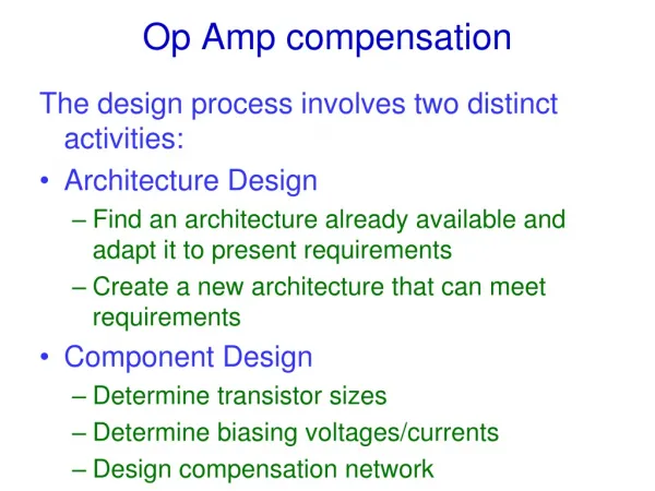
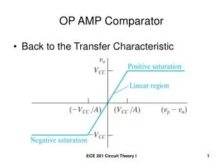
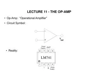
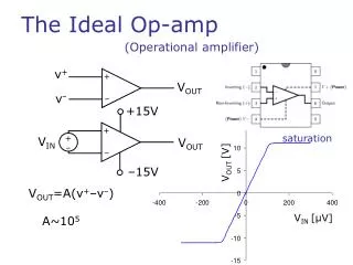
v +. V OUT. v –. +15V. +. +. –15V. –. –. +. –. The Ideal Op-amp. (Operational amplifier). saturation. V IN. V OUT. V OUT [V]. V OUT =A(v + –v – ). V IN [ μ V]. A~10 5. v +. v –. v +. V IN. V OUT. v –. R 1. R 2. Non-Inverting Amplifier Circuit. +. +. –. –. V OUT.

E N D
v+ VOUT v– +15V + + –15V – – + – The Ideal Op-amp (Operational amplifier) saturation VIN VOUT VOUT [V] VOUT=A(v+–v–) VIN [μV] A~105
v+ v– v+ VIN VOUT v– R1 R2 Non-Inverting Amplifier Circuit + + – – VOUT Op-amp Feedback
v+ v– v+ VIN VOUT v– R1 R2 Non-Inverting Amplifier Circuit + + – – Op-amp Feedback Assumptions: Gain is very large (A) Inputs draw no current (ZIN=) Output attempts to make input voltage difference zero (v+=v–)
Inverting Amplifier Circuit R2 i R1 v– VIN – i VOUT v+ + R1 R1 R1 V1 V3 V2 R2 i v– – VOUT Summing amplifier v+ +
R1 R2 R3 V1 V2 V3 RF i v– – VOUT v+ +
Difference amplifier R2 R1 v– V1 – VOUT v+ R1 + V2 R2
Integrator VOUT VIN Capacitor as integrator R Vi Vint C If RC>>t VC<<Vi
i v– – i v+ Op-amp Integrator C R VIN VOUT +
Differentiation C Vi Vdiff R Small RC
i v– – i v+ Op-amp Differentiator VOUT VIN R C VIN VOUT +
Complex analysis R2 i C R1 v– – i VOUT v+ V0ejωt + High pass filter
v+ VOUT v– + – Exploiting op-amp saturation Saturation voltage VOUT = A(v+–v–) A VOUT = +VSat v+>v– VOUT = –VSat v+<v–
+ – Bridge circuits Z1 Z3 VA VB V0 VOUT Z4 Z2 Bridge balanced when VAVB=0
+ + + + – – – – Analogue – digital conversion (ADC) V0 R R VIN R R
R VOUT + C R1 R1 Oscillator
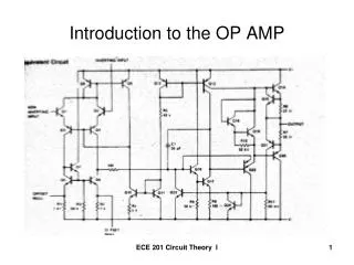
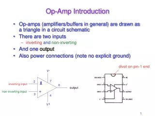
Op-amp applications Building block of analogue electronics Signal amplifiers Audio amplifiers Integrators / differentiators Voltage / current sources Active filters Oscillators Digital-analogue and analogue-digital convertors