THE FOUR STROKE CYCLE
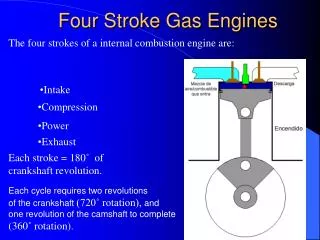
LET’S LOOK IN MORE DETAIL. THE FOUR STROKE CYCLE. BUT HOW DOES IT WORK EXACTLY?. WE KNOW ABOUT:-. WHICH WE KNOW AS:-. 1. INDUCTION. SUCK. 2. COMPRESSION. SQUEEZE. 3. COMBUSTION. BANG. 4. EXHAUST. BLOW. AND RELATE IT TO THIS DIAGRAM.


THE FOUR STROKE CYCLE
E N D
Presentation Transcript
LET’S LOOK IN MORE DETAIL THE FOUR STROKE CYCLE BUT HOW DOES IT WORK EXACTLY? WE KNOW ABOUT:- WHICH WE KNOW AS:- 1. INDUCTION SUCK 2. COMPRESSION SQUEEZE 3. COMBUSTION BANG 4. EXHAUST BLOW
AND RELATE IT TO THIS DIAGRAM WE’LL SEE A STEP BY STEP EXPLAINATION OF THIS DIAGRAM Operating Cycle
AND THIS DIAGRAM Down Up Up Down 1 ‘Stroke’ = the piston sliding either up or down the cylinder Therefore a ‘Four’ Stroke engine is 2 revs of the crankshaft Operating Cycle
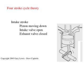
PISTON MOVES DOWN CYLINDER AIR/FUEL DRAWN (INDUCED - SUCKED) INTO CYLINDER CRANK ROTATES TDC STROKE 1 BDC Operating Cycle
PISTON MOVES BACK UP CYLINDER AIR/FUEL TRAPPED (COMPRESSED - SQUEEZED) IN CYLINDER CRANK CONTINUES TO ROTATE TDC STROKE 2 BDC Operating Cycle
PISTON FORCED DOWN CYLINDER AIR/FUEL IGNITED AND BURNS (COMBUSTION - BLOW) IN CYLINDER CRANK STARTS 2ND ROTATION TDC STROKE 3 BDC Operating Cycle
PISTON MOVES BACK UP CYLINDER AGAIN BURNT AIR/FUEL PUSHED OUT OF CYLINDER (EXHAUST – BLOW) CRANK CONTINUES 2ND ROTATION TDC STROKE 4 BDC Operating Cycle
It is of course the start of the induction stroke When the end of the exhaust stroke is reached And the whole process starts again Operating Cycle
But :- Because valves don’t open and close instantly, and the air/fuel mixture doesn’t explode instantly (it’s a rapid burning process) valve operation and air/fuel ignition isn’t set at the TDC and BDC positions. These events are set to occur at the following positions, designated as angular positions of the crank shaft. Operating Cycle
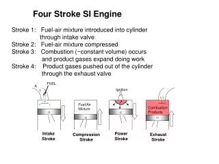
At which point, the Inlet valve begins to open The start of Induction – Stroke 1 We’ll start the process at 30 degrees before TDC TDC BDC Operating Cycle
When the Inlet valve closes The start of Compression – Stroke 2 The induction stroke ends at 15 degrees after BDC. TDC Inlet valve opens 1. Induction Trapping the air/fuel mixture in the cylinder BDC Inlet valve closes Operating Cycle Called Valve Lag because it is after BDC
At this point, both valves are closed Ignition The start of Power – Stroke 3 Ignition occurs at 30 degrees before TDC. TDC Inlet valve opens 1. Induction 2. Compression And is the start of the Power stroke BDC Inlet valve closes Operating Cycle
15 degrees before BDC, the exhaust valve opens Exhaust valve opens The start of Exhaust – Stroke 4 Burning air/fuel mixture reaches maximum expansion TDC Inlet valve opens And is the end of the Power stroke and start of the Exhaust stroke Ignition 3. Power 1. Induction 2. Compression Called Valve Lead because it is before BDC BDC Inlet valve closes Operating Cycle
So as the exhaust valve starts to close, the inlet valve starts to open The end of Exhaust – Stroke 4 This position is towards the end of the Exhaust stroke TDC Inlet valve opens Ignition 2. Compression 3. Power 1. Induction 4. Exhaust And is ALSO the beginning of the Induction stroke Exhaust valve opens BDC Inlet valve closes Operating Cycle
Both the inlet and exhaust valves are partially open Valve Overlap - Stroke 4 to 1 This is called ‘Valve Overlap’ TDC Exhaust valve closes Inlet valve opens Ignition 2. Compression 3. Power 1. Induction 4. Exhaust Therefore the Induction stroke starts 45 degreesbefore the end of the Exhaust stroke Exhaust valve opens BDC Inlet valve closes Operating Cycle
The exhaust valve is now closed The inlet valve is now open The start of Induction – Stroke 1 This position is at the end of the exhaust stroke TDC Exhaust valve closes Inlet valve opens Ignition 2. Compression 3. Power 1. Induction 4. Exhaust And is 45 degrees into the induction stroke Exhaust valve opens BDC Inlet valve closes Operating Cycle
Simple isn’t it! Suck Squeeze Bang Blow Operating Cycle
But, this is happening in every cylinder in all 4 stroke engines no matter how many cylinders there are. Lets look at the most typical vehicle engine, the ‘Inline 4’ Operating Cycle
And the firing order is:- The cylinders are numbered from 1 – 3 – 4 - 2 to the rear the front Operating Cycle