Network Protocols
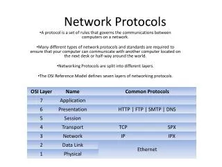
This document discusses the importance of formal methods in the development of communication protocols, highlighting the role of Finite State Machines (FSMs) in ensuring correctness and reliability. It contrasts traditional informal processes with mathematically-based techniques that provide rigorous specifications, validation, and conformance testing. The paper delves into protocol specification, synthesis, and performance analysis, offering insights into the structure and functioning of FSMs, as well as their application in real-world scenarios like communication software development.

Network Protocols
E N D
Presentation Transcript
NETW 703 Network Protocols Finite State Machines (FSMs) Dr. Eng Amr T. Abdel-Hamid Winter 2006
Protocol Engineering • Application of formal methods + software engineering in the development of communication software • Traditional development process is informal • Informal textual documentation • Graphical description techniques • Structural analysis and design • Lack scientific foundation • Lead to ambiguous definition of the desired features • Offer no means to prove the completeness and consistency of the system • Problems in financial cost and commercial release 2/31
Formal Methods for Protocol Development • Mathematically-based techniques that provide a rigorous basis for software development, leading to correctness and reliability in various steps • Provide a formal and unambiguous way of designing and documenting protocols • Protocol modeling & specification • Protocol synthesis • Allow formal analysis before protocols are implemented • Protocol verification & validation • Protocol performance analysis • Allow automatic and direct generation of • Executable programs from the formal specification • Test cases for conformance testing 3/31
Protocol Engineering Blocks • Service specification is the document that describes how a protocol layer provides network services to its users or protocol modules in the upper layers • Protocol specification is the documentation that describes the message format and exchange sequences among the protocol modules of the layer, which realizes the service specification • Protocol synthesis is the process that takes the service specification and generates the error-free protocol specification, or combines multiple protocol specifications (phases) into an error free protocol specification • Protocol implementation is the process that takes the protocol specification and develops the protocol software modules • Protocol validation/verification is the process that verifies if the protocol specification actually realizes the service specification. Validation sometimes refers to check the protocol specification will not get into deadlock, unspecified reception, and livelock errors • Conformance testing is the process that given a protocol specification, generate the short test suite for testing the protocol implementation (software modules) 4/31
Protocol Specification • State Transition Models • FSM (Finite State Machines), EFSM (Extended FSM), CFSM (Communicating FSM) • LTS (Labeled Transition Systems), IOA (Input-Output Automata), Petri Nets, • Programming Languages Models • Abstract Programs • CCS (Calculus of Communicating systems), CSP (Communicating Sequential Processes) • Temporal logic • Hybrid Models • Language Standards • SDL (FSM + extensions) • Estelle (EFSM + extended Pascal) • LOTOS (CCS) 5/31
FSM Overview • Finite State Machine is a tool to model the desired behavior of a sequential system. • The designer has to develop a finite state model of the system behavior and then designs a circuit that implements this model • A FSM consists of several states. Inputs into the machine are combined with the current state of the machine to determine the new state or next state of the machine. • Depending on the state of the machine, outputs are generated based on either the state or the state and inputs of the machine. 6/31
FSMs States • Current State: State which determines the current behavior of the machine • Next State: State which machine will have after processing an input event. Next State can be the same as current state • Start State: State in which machine will be when created (power on) • End State: State in which no transition rule is executable 7/31
Transitions • Triggered by input events the FSM moves from one state to other based on the Transition Function • Transition Function produces the Output and Next State depending on Current State and Input Event • While in particular state FSM is not active, it is waiting for an input to perform next activity 8/31
S0 State Transition Diagrams • Used to visually represent an FSM • Emphasis is on identifying states and possible transitions • Circles represent States • Arrows represent Transitions Transitions 01/11 Initial State S1 Input/Output 01/01 01/10 11/10 011/00 S3 S2 1-/11 State 9/31
Finite State Machines (FSMs) • Finite state machines consist of: • States • Input Events (or Signals, or Messages) • Transition Functions • Output Events Output Events States Transition Functions Input Events 10/31
Kiss2 Format • STG and Tables are only ways to represent FSMs • Other techniques are available, Example: Keep it simple stupid trails.kiss2 .i 2 .o 1 .p 11 .s 4 -0 st0 st0 0 11 st1 st3 0 ………. 11/31
FSM Example • General Machine Description: • deliver package of gum after 15 cents deposited • single coin slot for dimes, nickels • no change 12/31
D D Vending Machine Example Reset 0¢ N 5¢ N 10¢ N, D 15¢ [open] 13/31
Mealy FSM • Output is dependent on the inputs and the current state transition condition 1 /output 1 state 2 state 1 transition condition 2 /output 2 14/31
Moore FSM • Output is dependent only on the current state transition condition 1 state 2 / output 2 state 1 / output 1 transition condition 2 15/31
Moore vs. Mealy FSM • Moore and Mealy FSMs can be functionally equivalent • Equivalent Mealy FSM can be derived from Moore FSM and vice versa • Mealy FSM Has Richer Description and usually requires smaller number of states • Smaller circuit area • Mealy FSM computes Outputs as soon as Inputs change • Mealy FSM responds one clock cycle sooner than equivalent Moore FSM • Moore FSM has no combinational path between Inputs and Outputs • Moore FSM is more likely to have a shorter critical path 16/31
Mealy FSM - Example • Mealy FSM that Recognizes Sequence “10” 0 / 0 1 / 0 1 / 0 S0 S1 0 / 1 Meaning of states: • S0: No elements of the sequence observed • S1: “1” observed 17/31
Moore FSM - Example • Moore FSM that Recognizes Sequence “10” 0 1 0 S0 / 0 1 S1 / 0 S2 / 1 1 reset 0 Meaning of states: • S0: No elements of the sequence observed • S1: “1” observed • S2: “0” observed 18/31
Formal definition • An FSM is a 6-tuple F<S, I, O, F, H, s0> • S is a set of all states {s0, s1, …, sl} • I is a set of inputs {i0, i1, …, im} • O is a set of outputs {o0, o1, …, on} • F is a next-state function (S x I → S) • H is an output function (S → O) • s0 is an initial state • Moore-type: Associates outputs with states (as given above, H maps S → O) • Mealy-type: Associates outputs with transitions (H maps S x I → O) 19/31
Categories of Finite State Machines • Complete FSM (CFSM) • Completely specified finite state machine • Specification domain is on the whole space • Partial FSM (PFSM) • Partially specified finite state machine • Specification domain is part of the whole space • Implementations are usually modeled by CFSM, while specifications could be CFSM or PFSM 20/31
FSM Example – Telephone • What are possible states • What are possible events • Create FSM Table • Create State Transition Diagram 21/31
Telephone States • States: • IDLE no calls in progress handset is on-hook • DIALING handset is off-hook, but call is not in progress • RINGING handset is on-hook, incoming call alert • TALKING handset in off-hook and call is in progress • Relevant Transitions (events) are: • off-hook User takes handset off-hook • on-hook User places handset on-hook • dial digit User dials digit • call alert Exchange alerts phone - incoming call 22/31
Modeling of Complex Systems • Typical telecomm system is too complex to be represented with a single FSM. As usually when dealing with complexity we should split a complex problem into a number of smaller components • In this case we will have number of concurrent FSMs communicating with each other. Communicating FSM can be • In a single process (task, thread of control) • In separate concurrent processes on same microprocessor • On separate microprocessors communicating to each other • Depending on how FSMs are co-located, different methods of communications are possible • The two communication mechanisms for concurrent processes can be categorized into Message Passing and Shared Data 23/31
Communication Mechanisms forConcurrent Systems • Message passing involves sending and receiving messages through a channel • In the Shared Memory approach memory is common to both processes, and they can read and write to the memory 24/31
Asynchronous & Synchronous Communications • Two approaches to implement message passing • Synchronous Communication • The processes involved in communication are required to participate at the point of communication simultaneously • If Process A attempts to send a message and Process B is not ready to receive it, Process A must wait until Process B is ready • Asynchronous Communication • The processes involved in communication are not required to participate at the point of communication simultaneously • If Process A attempts to send a message and Process B is not ready to receive it, Process A sends it anyway 25/31
Asynchronous Communication using FIFOs • Asynchronous communication requires use of buffers to store messages • The protocol specification methods studied in this course will be mostly based upon Asynchronous Communication • In most communicating systems, a FIFO (First In First Out) discipline is enforced on sending and receiving messages • During a send event the message is appended to the end of the queue while a receive event removes a message from the front • It is possible to modify the communications channel to provide additional communication constructs such as priority signals 26/31
Clayton Tunnel (CFSM Example) train in tunnel Is Train Out? Stop Worker A Train 1 Worker B tunnel is clear tunnel is clear 27/31
Communicating FSMs Model • Protocol is described as a set of Communicating FSMs (CFSMs) • Each CFSM represents a component (or process) of the network • In OSI term, a protocol entity, e.g. sender, receiver • Each process can be defined by a set of states • The process waits in a state for an event to occur • Messages are received as events by the receiving FSM • When this input event occurs, it transfers to another state, and in doing so can send out messages and performs other tasks • Each CFSM is represented by a directed labeled graph where • Nodes represent states (conditions) of the process • Edges represent transitions (events) of the process • This model is the model used by the ITU Specification and Description Language (SDL) 28/31
Communicating FSMs Model Sender Receiver process 01/01 S1 01/11 S0 00/10 29/31
Transitions • Transitions are triggered by actions • Internal the process (e.g. the sending of a message) or • External stimuli (e.g. the reception of a message) • The sending message transition is labeled as -Msg • Where Msg is the type of messages being sent • The receiving message transition is labeled as +Msg • Where Msg is the head message on the incoming FIFO queue of the CFSM 30/31
Operation Semantics (Rules) • Channels that connect CFSM's are assumed to be FIFO queues • Starting at the initial node, a CFSM traverses the nodes and transitions • Nodes (states) • Initial node - starting state of a CFSM • Final node - no transition • Receiving node - all outgoing transitions are receiving transitions. If no message or incorrect msg in the channel, the node will be blocked • Sending node - all outgoing transitions are sending transitions. • Mix node -- has both receiving and sending transition 31/31
CFSM Operating Semantic (cont.) • Transitions • When a machine traverses a sending transition, it sends/appends a message with the same label to its outgoing channel • A machine at a node cannot traverse its receiving transition unless there is a message matched with the same label on the head of its incoming channel • When a machine traverses a receiving transition, it removes the matched head message of its incoming channel • Among several possible transitions, a machine traverses one non-deterministically 32/31
Examples Of CFSMs • Example 1: Simple stop-and-wait protocol • Example 2: A sliding window protocol with a window size of 2 33/31
Pros and Cons of the CFSM model • The overall state of the system can be described by a vector of all the states of the individual processes. Then the overall system state itself becomes a finite state machine, and thus its behavior becomes more deterministic • CFSM deals only with the state-transition aspect of protocols, It does not address the data aspect of protocols, e.g., message content or format • It can not handle protocols where state variables have a wide range of values. Extended FSM were proposed but EFSM becomes difficult to analyze 34/31