Download
1 / 12
130 likes | 269 Views
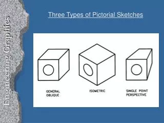
This lecture delves into the fundamentals of isometric projections, outlining key terminology and techniques used in engineering graphics. It explains the concept of isometric axes, lines, and planes, differentiating between isometric and non-isometric elements. Students will learn how to create accurate isometric drawings, apply box construction methods, and understand the representation of angles and irregular objects. The session emphasizes the importance of maintaining scale and detail in drawings, equipping students with essential skills for visualizing three-dimensional objects.

E N D
ENGINEERING GRAPHICS1E7 Lecture 5: Isometric Projections
Isometric Terminology • The three coordinate axes are called isometric axes • Any line parallel to isometric axes is called isometric line • A non-isometric line is a line not parallel to any one of the three isometric axis • In isometric projection of cube, the faces of the cube and any plane parallel to them is called isometric planes
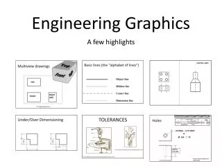
Notes • Objects composed entirely of isometric lines can be drawn by taking all measurements parallel to main edges of the enclosing box. • In an isometric drawing, an angle never appears in its true size. • Non-isometric lines are drawn by transferring the ordinates (which are on isometric lines) of the end of the lines
Objects with Normal Surfaces Make an Isometric Drawing with corner A at the bottom
NON-ISOMETRIC LINE Objects with Oblique Surfaces • Make an Isometric Drawing with corner A at the bottom
Objects with Non-isometric Lines • Make an Isometric Drawing with apex A facing front
Objects with Non-isometric Lines • Non-isometric lines are drawn with box construction and offset measurements • Non-isometric lines are not drawn in true length in isometric drawing (BA is shorter than CA in this drawing)
Irregular Objects • Make an Isometric Drawing of the following irregular object (pyramid)
Irregular Objects • OA and OB offsets help to locate apex O • Complete box construction may not be needed in each case
Notes • Axonometric projection shows all 3 dimensions, length, width and height • The isometric lines are only drawn to scale. • Inclined and oblique surfaces are drawn using end coordinates • Angles, irregular curves require special techniques • Box construction and offset measurements are common methods