Understanding Addressing Modes and Registers in 8088 Microprocessors
This document explores the intricate details of addressing modes and registers in the 8088 microprocessor architecture as taught by Dr. Eng. Amr T. Abdel-Hamid during Fall 2011. It highlights the organization of the address bus, explains the different types of general-purpose registers (like AX, BX, CX, DX), and provides insights into the execution unit's operations. It covers instruction machine codes, the structure of machine code, the importance of operands, and the functionality of flag registers. This guide is essential for anyone looking to deepen their understanding of micro-computer applications.

Understanding Addressing Modes and Registers in 8088 Microprocessors
E N D
Presentation Transcript
ELECT 707 Micro-Computer Applications: Addressing Modes Dr. Eng. Amr T. Abdel-Hamid Fall 2011
Organization of 8088 Address bus (20 bits) AH AL General purpose register BH BL CH CL Execution Unit (EU) DH DL Data bus (16 bits) SP CS Segment register BP DS SI SS DI ALU Data bus (16 bits) ES IP Bus control ALU Instruction Queue External bus EU control Flag register Bus Interface Unit (BIU)
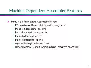
Instruction Machine Codes • Instruction machine codes are binary numbers • For Example: 1 0 0 0 1 0 0 0 1 1 0 0 0 0 1 1 MOV AL, BL Register mode MOV • Machine code structure Opcode Mode Operand1 Operand2 • Some instructions do not have operands, or have only one operand • Opcode tells what operation is to be performed. • EU control logic generates ALU control signals according to Opcode) • Mode indicates the type of a instruction: Register type, or Memory type • Operands tell what data should be used in the operation. Operands can be addresses telling where to get data (or where to store results)
EU Operation 1. Fetch an instruction from instruction queue 2. According to the instruction, EU control logic generates control signals. (This process is also referred to as instruction decoding) 3. Depending on the control signal, EU performs one of the following operations: • An arithmetic operation • A logic operation • Storing a datum into a register • Moving a datum from a register • Changing flag register
Registers • A register is a storage element inside a microprocessor. • Almost all operations would involve using registers. • Some registers are general purpose registers, while others have special purposes. • General purpose registers can hold various data sizes and used for almost any purpose as dictated by the program. • However, each general purpose register does have its own special purposes.
Registers • Since the x86 instruction set is designed to be compatible with previous microprocessors, the same register can be accessed using different names. • Different names are given for 64-bit, 32-bit, 16-bit and 8-bit version of the same register.
General Purpose Registers • RAX, EAX, AX (AH & AL) • A general purpose register • Also an accumulator – stores intermediate results after arithmetic and logic operations • Can also hold the offset address of a location in memory (80386 and above) • RBX, EBX, BX (BH & BL) • A general purpose register • Also a base index register – holds the offset address of a location in memory • Can also address memory data (80386 and above)
General Purpose Registers • RCX, ECX, CX (CH & CL) • A general purpose register • Also a count register – holds the count for various instructions • Can also hold the offset address of a location in memory (80386 and above) • RDX, EDX, DX (DH & DL) • A general purpose register • Also a data register – stores data related to accumulator’s calculation (multiply and divide) • Can also address memory data (80386 and above)
General Purpose Registers • RBP, EBP, BP • A general purpose register • Also a base pointer register – points to a memory location for memory data transfer • RDI, EDI, DI • A general purpose register • Also a destination index register – holds the memory address for the destination data of a string instruction
General Purpose Registers • RSI, ESI, SI • A general purpose register • Also a source index register - holds the memory address for the source data of a string instruction • R8 through R15 • General purpose registers • Found only in 64-bit microprocessors • Data are addressed in 64-, 32-, 16-, or 8-bitsizes
Special Purpose Registers • RIP, EIP, IP • Instruction pointer – points to the next instruction in the memory to be executed • RSP, ESP, SP • Stack pointer – points to an area in memory called the stack • RFLAGS, EFLAGS, FLAGS • Indicates the condition of the microprocessor and control its operation
Flags • The C, P, A, Z, S and O flags are changed by most arithmetic and logic operations. • Flags never change for any data transfer or program control operations. • Some flags are also used to control features found in the microprocessor.
Flags • Descriptions for some of the flag bits: • C (carry): holds the carry after addition or borrow after subtraction. • P (parity): the count of 1s in a number expressed as even or odd. • 0 for odd, 1 for even. • A (auxiliary carry): holds the half-carry after addition or the borrow after subtraction between bit positions 3 and 4 of the result.
Flags • Z (zero): shows that the result of an arithmetic or logic operation is zero. • 0 result is not zero, 1 result is zero. • S (sign): holds the arithmetic sign of the result after an arithmetic or logic instruction executes. • 0 for positive, 1 for negative. • T (trap): enables trapping through an on-chip debugging feature. • 0 disable trapping, 1 enable trapping. • If enabled, allows the microprocessor to interrupt the flow of the program on conditions indicated by the debug registers and control registers. • Microsoft Visual Studio debugging tool uses this feature.
Flags • I (interrupt): control the operation of the INTR (interrupt request) input pin. • 0 disables INTR pin, 1 enables INTR pin. • D (direction): selects increment or decrement mode for SI/DI registers. • 0 increment, 1 decrement. • O (overflow): indicates that the result of an addition/subtraction of signed numbers exceeded the capacity of the machine.
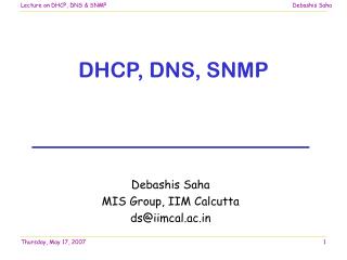
15 0 CS Code Segment DS Data Segment Stack Segment SS ES Extra Segment Memory Segmentation • A segment is a 64KB block of memory starting from any • 16-byte boundary • For example: 00000, 00010, 00020, 20000, 8CE90, and E0840 are all valid segment addresses • The requirement of starting from 16-byte boundary is due to the 4-bit left shifting • Segment registers in BIU
Generating Memory Addresses • How can a 16-bit microprocessor generate 20-bit memory addresses? Left shift 4 bits FFFFF 16-bit register 0000 Addr1 + 0FFFF Segment (64K) + 16-bit register Offset Offset Addr1 20-bit memory address Segment address 00000 1M memory space Intel 80x86 memory address generation
8088 Memory CS 1 2 3 9 IP 0 0 1 2 123A2 MOV AL, 0 1 2 3 A 2 Fetching Instructions • Where to fetch the next instruction? • Update IP • After an instruction is fetched, Register IP is updated as follows: IP = IP + Length of the fetched instruction • For Example: the length of MOV AL, 0 is 2 bytes. After fetching this instruction, the IP is updated to 0014
1 2 3 4 0 (assume DS=1234H) DS 0 3 0 0 Memory address 1 2 6 4 0 (assume DS=1234H) 1 2 3 4 0 DS 0 3 1 0 (assume SI=0310H) Memory address 1 2 6 5 0 Accessing Data Memory • There is a number of methods to generate the memory address when accessing data memory. These methods are referred to as Addressing Modes • Examples: • Direct addressing: MOV AL, [0300H] • Register indirect addressing: MOV AL, [SI]
A memory system showing the placement of four memory segments. • a memory segment can touch or overlap if 64K bytes of memory are not required for a segment • think of segments as windows that can be moved over any areaof memory to access data or code • a program can have more than four or six segments, • but only access four or six segments at a time
1 2 3 4 0 (assume DS=1234H) DS 0 3 0 0 Memory address 1 2 6 4 0 (assume DS=1234H) 1 2 3 4 0 DS 0 3 1 0 (assume SI=0310H) Memory address 1 2 6 5 0 Accessing Data Memory • There is a number of methods to generate the memory address when accessing data memory. These methods are referred to as Addressing Modes • Examples: • Direct addressing: MOV AL, [0300H] • Register indirect addressing: MOV AL, [SI]
MOV instruction provides a basis for explanation of data-addressing modes DATA ADDRESSING MODES opcode • an opcode, or operation code, tells the microprocessor which operation to perform
MOV BX, CX • The source register’s contents do not change. • the destination register’s contents do change • The contents of the destination register or destination memory location change for all instructions except the CMP and TEST instructions. • Note that only the rightmost 16 bits of register EBX change. The MOV BX, CX instruction does not affect the leftmost 16 bits of register EBX.
Important for instructions to use registers that are the same size. • never mix an 8-bit \with a 16-bit register, an 8- or a 16-bit register with a 32-bit register • this is not allowed by the microprocessor and results in an error when assembled
Immediate Addressing • Term immediate implies that data immediately follow the hexadecimal opcode in the memory. • immediate data are constant data • data transferred from a register or memory location are variable data • Immediate addressing operates upon a byte or word of data.
MOV EAX,3456H Before the instruction executed After the instruction executed • the source data overwrites the destination data.
In symbolic assembly language, the symbol # precedes immediate data in some assemblers. • MOV AX,#3456H instruction is an example • Most assemblers do not use the # symbol, but represent immediate data as in the MOV AX,3456H instruction. • an older assembler used with some Hewlett-Packard logic development does, as may others • in this text, the # is not used for immediate data
The symbolic assembler portrays immediate data in many ways. • The letter H appends hexadecimal data. • If hexadecimal data begin with a letter, the assembler requires the data start with a 0. • to represent a hexadecimal F2, 0F2H is usedin assembly language • Decimal data are represented as is and require no special codes or adjustments. • an example is the 100 decimal in theMOV AL,100 instruction
An ASCII-coded character or characters may be depicted in the immediate form if the ASCII data are enclosed in apostrophes. • Binary data are represented if the binary number is followed by the letter B. • in some assemblers, the letter Y
Labels • Each statement in an assembly language program consists of four parts or fields. • The leftmost field is called the label. • used to store a symbolic name for the memory location it represents • All labels must begin with a letter or one of the following special characters: @, $, -, or ?. • a label may any length from 1 to 35 characters • The label appears in a program to identify the name of a memory location for storing data and for other purposes. NEXT: MOV AX, [BX] ; next element
The next field to the right is the opcode field. • designed to hold the instruction, or opcode • the MOV part of the move data instruction is an example of an opcode • Right of the opcode field is the operand field. • contains information used by the opcode • the MOV AL,BL instruction has the opcode MOV and operands AL and BL • The comment field, the final field, contains a comment about the instruction(s). • comments always begin with a semicolon (;) NEXT: MOV AX, [BX] ; next element
Direct Data Addressing • Applied to many instructions in a typical program. • Two basic forms of direct data addressing: • direct addressing, which applies to a MOV between a memory location and AL, AX, or EAX • displacement addressing, which applies to almost any instruction in the instruction set • Address is formed by adding the displacement to the default data segment address or an alternate segment address.
Direct Addressing • Direct addressing with a MOV instruction transfers data between a memory location, located within the data segment, and a register. • usually a 3-byte long instruction MOV CX,DATA • loads CX from the data segment memory location DATA (1234H). • DATA is a symbolic memory location, while1234H is the actual hexadecimal location
Direct Data Addressing • Example • DS=1512H • MOV AL, 99H • MOV [3518], AL After execution memory location • Logical address DS:3518 • Physical address18638 • will have 99H
Register Indirect Addressing • Allows data to be addressed at any memory location through an offset address held in any of the following registers: BP, BX, DI, and SI. • In addition, 80386 and above allow register indirect addressing with any extended register except ESP. • In the 64-bit mode, the segment registers serve no purpose in addressing a locationin the flat model.
MOV AX,[BX] BX = 1000H and DS = 0100H. Register Indirect Addressing
The data segment is used by default with register indirect addressing or any other mode that uses BX, DI, or SI to address memory. • If the BP register addresses memory, the stack segment is used by default. • these settings are considered the default forthese four index and base registers • For the 80386 and above, • EBP addresses memory in the stack segment by default. • EAX, EBX, ECX, EDX, EDI, and ESI address memory in the data segment by fault.
Base-Plus-Index Addressing • Similar to indirect addressing because it indirectly addresses memory data. • The base register often holds the beginning location of a memory array. • the index register holds the relative positionof an element in the array • whenever BP addresses memory data, both the stack segment register and BP generate the effective address
Locating Data with Base-Plus-Index Addressing MOV DX,[BX + DI] • The Intel assembler requires this addressing mode appear as [BX][DI] instead of [BX + DI]. • The MOV DX,[BX + DI] instruction is MOV DX,[BX][DI] for a program written for the Intel ASM assembler.
Base-plus-index addressing mode MOV DX,[BX + DI] DS=0100H, BX=1000H and DI=0010H memory address 02010H is accessed because
An example of the base-plus-index addressing mode. Here an element (DI) of an ARRAY (BX) is addressed.
Register Relative Addressing • Similar to base-plus-index addressing and displacement addressing. • data in a segment of memory are addressed by adding the displacement to the contents of a base or an index register (BP, BX, DI, or SI)