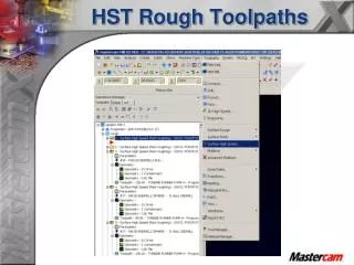
HST Rough Toolpaths
HST Rough Toolpaths. Cut Parameters. Note: The cut parameters will change based on the toolpath type. When possible the same settings will be brought into the new toolpath type. Cut Parameters. Turn on the “Add cuts” option.

HST Rough Toolpaths
E N D
Presentation Transcript
Cut Parameters Note: The cut parameters will change based on the toolpath type. When possible the same settings will be brought into the new toolpath type.
Cut Parameters Turn on the “Add cuts” option Stepdown – Determines the Z spacing between adjacent cutting passes Add cuts- Activates the adaptive stepdown feature, which add cuts at the shallow areas of the profile so that the toolpath does not have excessively large horizontal spacing between cutting passes Min stepdown – Specifies the minimum stepdown value when Add cuts is activated. Passes will be no less than this distance from each other – in the z axis
Cut Parameters Max profile stepover – Determines the maximum change in the surface profiles for two adjacent cutting passes. This represents the maximum value of the shortest horizontal distance between adjacent points on the two profiles. Max profile stepover – is the thickness of the scallop. If the thickness exceeds the .250 setting then a z cut is added to bring the thickness under the .250 setting.
Cut Parameters Notice the scallop thickness
Cut Parameters Max profile stepover
Cut Parameters Turn on the “Smoothing” option Smoothing – Replaces sharp corners with an arc for faster and smoother transitions in the tool direction.
Cut Parameters Max Radius – Enter the radius of the largest arc that you will allow Mastercam to insert to replace the corner. Larger arcs will result in a smoother toolpath but with greater deviation from the originally programmed toolpath Profile Tolerance – The maximum distance that the outermost profile of the smoothed toolpath that will deviate from the original toolpath Offset tolerance – This is the same measurementas the profile tolerance but is applied to all of the profiles except the outermost one. This lets you maintain different tolerances for the subsequent profiles.
Cut Parameters Possible to leave different amounts of stock for floor and wall surfaces. Note: Can’t leave less stock on the walls than the floor
Transition Use this page to configure the entry move that the tool will make as it transitions to new Z levels. Note: Core Roughing, Area Clearance, Rest Roughing and Horizontal use these parameters
Transition Radius - Enter the radius of the entry helix. If the profile is too small for a helix ramp of this diameter, Mastercam will create a profile ramp instead. Output arc moves - Select this option to have Mastercam create the helix with arc moves. De-select this option the helix will be rendered with many small linear moves. Z Clearance - This is an extra height used in the ramping motion down from a top profile. Plunge angle - The ramps into the cut will be no greater than this value Note: If tool can’t fit with Helical Entry settings then Ramp Entry is used.
Transition Z clearance - This is an extra height used in the ramping motion down from a top profile Plunge angle - The ramps into the cut will be no greater than this value. Preferred profile length- Enter a minimum size for the profile in order for a ramp to be created. Skip pockets smaller than - Use this value to specify a minimum distance across the pocket that Mastercam will consider creating a cutting pass for.
Transition Preferred profile length Top View Iso View
Transition Preferred profile length Top View Iso View
Transition Note: Both “Entry Helix” and “Profile Ramp” both use these settings
Steep/Shallow Z Depth
Steep/Shallow Use Z depths - Select this option to limit the machining zone to the area between the depths entered in this section. Detect limits- Automatically populate the Minimum and Maximum depth fields with the highest and lowest points on your drive surfaces.
Linking Parameters Linking - Use this page to create the links between the cutting passes. In general, you can think of linking moves as air moves when the tool is not in contact with the part.
Linking Parameters Retracts - This determines how the tool will move between the end of one pass and the beginning of another The “Curl up” and ‘Curl Down” will be grayed out unless “Minimum Distance” is selected.
Linking Parameters 2 & 5 3 6 4 1
Linking Parameters Min Distance - Inserts Curl up / Curl down high-speed arcs (.1683) to and from the retract height and maintains a Part clearance (.153) above the surface for the fastest transitions
Linking Parameters Min Distance
Linking Parameters Output feed move - Use this option to output the rapid move between passes as a feed rate move. Note: Since each machine is going to have a different max feed rate, this value is set from the machine definition.
Linking Parameters Output Feed move setting
Linking Parameters Part Clearance Minimum Vertical Retract – The tool retracts only as high as it needs to, to clear the part by the “part clearance” setting
Linking Parameters Full Vertical Retract Full Vertical Retract – The tool retracts to the “Clearance plane”
Linking Parameters Machine Entire Pass (finishing) –The path of the tool will match the surface, including vertical surfaces and the corners. An entry/exit arc will only be inserted at the end of the pass, and then only if it can be done safely without hitting the part. Minimize Trimming (roughing) – The path of the retract will be as close to the surface as possible, maintaining a minimum distance from the surface to fit the entry/exit arc. Fully Trim Pass (?)– Fully trim pass—The pass is trimmed back so the entire entry/exit arc fits into it, but no nearer than a full machine pass link would be. Select this option where it is important to prevent over-machining.
Reference Points Reference point - is a location that the tool moves to between the home (tool change) position and the start or end of the toolpath. You can create separate reference points for both approach and retract moves.
Arc Filter/Tolerance Filter ratio - The ratio of filter tolerance to cut tolerance. This ratio is automatically applied to the filter tolerance and cut tolerance. If Off, then Mastercam uses only the cut tolerance for the toolpath.
Arc Filter/Tolerance Toolpath Fillets: Theoretical fillets are created in sharp corners to keep the tool motion smooth and allow flat cutters to be used in roughing where fillets weren’t created in the model.
Arc Filter/Tolerance No toolpath fillets
Arc Filter/Tolerance Toolpath Fillets
Toolpath Type Rest Roughing Use a rest roughing toolpath when you want to calculate the cutting passes only on the stock left over from one or more previous roughing operations, similar to Restmill
Rest Roughing Rest Material
All previous operations - Calculates the remaining stock using all operations in the Toolpath Manager. This method determines the areas of stock where the tool did not go. One other operation - Calculates the remaining stock using all operations in the Toolpath Manager. This method determines the areas of stock where the tool did not go. Roughing tool - Calculates the remaining stock based on the diameter and corner radius of a tool. Cad file – Uses an STL file to calculate where the tool can remove material Rest Material
Lists the current operations in the operation manager Rest Material
Rest Material Stock resolution - Use a smaller value to tighten up the stock model and create a smoother restmill toolpath. Use a larger value to loosen the stock model and create a faster but rougher restmill toolpath.
Adjustments to remaining stock Rest Material Use remaining stock as computed – No adjustment to the stock model Adjust remaining stock to ignore small cusps – Use this setting to set the adjustment distance to reduce the stock model, this setting will find less material to machine Adjust remaining stock to mill small cusps – Use this setting to set the adjustment distance to increase the stock model, this setting will find more material to machine
Adjustments to remaining stock Rest Material Adjustment distance - Enter a value to expand or reduce the calculated stock model
Rest Material Roughing tool is a theoretical calculation. Note: With the “Skip pocket” setting its possible to have the tool plunge into material with the “Roughing Tool” setting