Download
1 / 31
360 likes | 818 Views
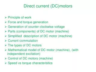
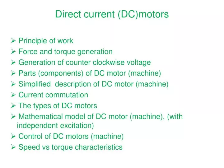
Direct current (DC)motors. Principle of work Force and torque generation Generation of counter clockwise voltage Parts (components) of DC motor (machine) Simplified description of DC motor (machine) Current commutation The types of DC motors

E N D
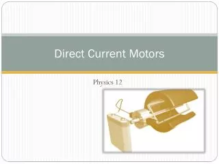
Direct current (DC)motors • Principle of work • Force and torque generation • Generation of counter clockwise voltage • Parts (components) of DC motor (machine) • Simplified description of DC motor (machine) • Current commutation • The types of DC motors • Mathematical model of DC motor (machine), (with independent excitation) • Control of DC motors (machine) • Speed vs torque characteristics
DC motors- Introduction • Advantages: • Leading role until 1960- years. • Almost ideal Speed vs Torque motor characteristics. • Possibilityofobtainingvariable and continuous dc voltage • Simplicity for control (controlparadigm) • Largerangeofspeedcontrollabilty • The lacks: • Mechanical commutator (inverter/rectifier) • Large moment of inertia (because of collector) • Request for often maintaining • Sensitivity according current overloading , sparking (in commutation)
Directcurrent (DC)motors Cross cutting of the DC motor
DC motors- Introduction Back-emf (E) and Force (F) definition (2) (1) • If armature winding is connected to thesupplyvoltage, theelectricalcurrentappears. Becauseofexistingmagneticfield (induction B), tangentialforce arise according to equation (2). • BecauseofforceF (2), torque is generated and pushthe rotor to rotate . • Whenthe rotor rotatinginmagneticfield, thevoltageE, equ1, is inducedin armature windingopposed to thevoltage U. Thisvoltage is called as “back-EMF” (backelectromotorforce) .Thisvoltage is proportional to rotor speedv, seeequ1). • Ifsupplied (armature) voltageinsteady state (constant rotor speed) is greaterthanback-emf, U>E, we are talkingabout motor work,(motoring) or motor mode ofoperation; otherwise, U<E we are talkingabout generator work.
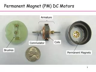
a) Description of DC motor components stator frame Covering of housing collector brushes and girder shaft armature bearing • Constructionof DC motor • The rotor is madeofslicediron (alternatedcurrentinthe rotor coils)!!. • Rotor windingconsistsof one or more solenoid (coils) whereeachofthem is connected to collector segment (slice), se picture bellow) • Stator is aimed for a excitation (electromagnetic or permanentmagnets)
b) Description of DC motor components • Stator: • Immobilepart, mademainlyofmassiveiron (yoke). It doesn’t belaminated. • Mainmagneticpoles (electromagnets) are fixed on stator andassuremagneticfields (B) inthe air-gap. Theamountofmagneticfieldcanbechangedonlyifelectromagneticexcitation is used. • Ifpermanent magnet is used for excitation, theamountofexcitationcannotbechanged! Excitationcoils pole’s shoes hausing
c) Description of DC motor components • Rotor (Armature): • Movingpart, madeofflaminatediron (becauseofalternatingcurrentin armature winding) • Rotor hasslotingswithcoilsin it. Rotor’s windingconsitsof one or more coilswhereeachof it is connected to collector. Felaminated Armature winding collector bearing shaft
rotor’s winding collector brush with girder d) Description of DC motor components Rotor (Armature):
e) Description of DC motor components Rotor (collector): Armature winding (coils) Slices (segments) on collector) brush brush girder Collector with brushes (mechanical commutator!!), we wil see that later!
f) Description of DC motor components • Collector’s segment is connected to rotor’s coil (as presented in the picture below). • Current flow from external source, over brush with girder and over collector’s slice enter into a coil (at the position of the neutral zone, where there are no induced voltage in this coil)! To rotor’s coil Coil connection to collector’s segment collector’s segment isolator brush Collector’s segment
g) Description of DC motor components Construction of torque and back-EMF (voltage E) • Magnetic field (permanent magnets) • two brushes • two collector’s segment • one coil in magnetic field
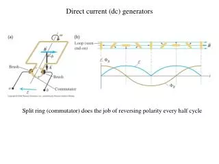
u i t collector = mechanical rectifier u t a) How DC motor works Forces under poles “S” and “N” results in equivalent torques on the coil under “S” pole and “N” pole. Current direction in the coil under pole S change its direction when the coil reach the position under N pole. This is the reason why we say that the current in armature winding, when looking from outside the motor, is ALTERNATE current!!! brush Current enter in the motor from source over collector and brushes in armature winding . Result is motor work. colector slice brush
b) How DC motor works Because magnetic field act on the arm which is changed according to sinusoidal low, then torque is changed in the same way.
DC motor ANIMATION – motor parts STATORpermanent magnet or electromagnet); ROTORarmature winding
DC motor – Animation Slots with coils in it PICTURE ANIMATION Red Magnet or electromagnet with “N” pole Green Magnet or electromagnet with “S” pole Stator may consist from more permanent magnets (multipole DC motor) Rotor coils are connected to collector (brown colour ), 3 pair of poles Brushes are dark-gray. Distance between collector slices is black.
DC motor as generator of DC voltage – animation System “brush-collector” rectifire alternate armature voltage in DC voltage .
DC motor – mathematical model Stacionarno stanje
The list of variables and constants • Ua, Ia Voltage and armature current • Ra, La Resistance and inductance of armature winding • Ea (Ei) back-emf • ce, ke constants of back-emf • cm, km torque constants • Mm, Mt motor torque and load torque • m, tmotor and load speed • Jm, Jt moment of inertia for motor and load • magnetic field, excitation
How to change the speed of motor? (1) Changing armature voltage (3) Changing armature resistor (2) Changing magnetic field (excitation)
(1) Changing armature voltage (a) • Historically, first qualitative control solution without considerable losses, see figure. • For high power ratings later is used system with asynchronous (induction) motors • Next solutions are Induction motor (AM ) which drive machine(generator G), in order to supply DC motor(M) with separate excitation. Controlling exciting current of generator G, the armature voltage (motor M voltage) is directly controlled. DC Motor M has constant excitation uum. • There is now new solution with power converter in motor armature for 4Q operation load
(1) Changing armature voltage (b) • This solution don’t use rotational machines for voltage change. Voltage is changed with static converter (in this situation it is simple diode and autotransformer). • The alternating voltage from the input side of transformer is changed by auto-transformer using slider on secondary transformer side. This voltage is rectifired using diode and forwarded then to the motor . • It is possible also to change the sign of motor excitation
(1) Changing armature voltage (c) • New solution with AC/DC converters in u armature. • Two 3-phase converters in antiparalel connection insure 4q operation with high dynamic performances. The change of current direction is realized electronically
(1) Changing armature voltage (d) (Speed vs Torque) simplicity of control, speed is proportional to the supplied voltage const.
(3) Changing armature resistance • In series with armature coil (winding), resistor is added. The slope of the characteristic is changed. • Rotor’s resistor as starter • For starting, the maximal resistor should be used, Rd4, (speed=0) , see figure • After start ,Rd3 resistor is added, and finally Rd=0 (R=Ra) is added • High losses, heating, not economical solution,
(3) Changing armature resistance (a) • It is used a lot in the past in DC traction drives. There were a lot of losses in energy conversion. (converted in heat). Steady state points in motoring and braking were set changing the amount of resistor added to armature circuit. Example is the tram. No efficient energy balance, great energy part is converted in the heat.
The types of the excitation systems for DC motors c) b) a) serial excitation Independent excitation paralel excitation
DC motor – region of speed control Konst. Controlled by armature voltage, magnetic field constant CONSTANT TORQUE region Controlled by magnetic field, Armature voltage constant , CONSTANT POWER region
current Flux (mag. field) torque armature voltage DC motor characteristics-variables of DC motor
Literature • http://www.physclips.unsw.edu.au/jw/electricmotors.html#DCmotors • http://electronics.howstuffworks.com/motor.htm • R.Wolf.”Fundamentals of electrical machines”, str.220-246, Školska knjiga, Zagreb, 1985. (Osnove električnih strojeva)