Download
1 / 25
250 likes | 529 Views
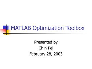
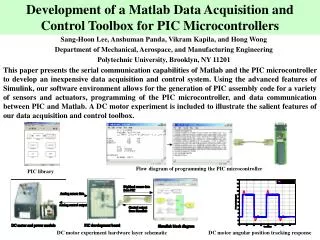
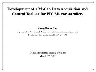
Development of a Matlab Data Acquisition and Control Toolbox for PIC Microcontrollers. Mechanical Engineering Seminar March 27, 2007. Sang-Hoon Lee Department of Mechanical, Aerospace, and Manufacturing Engineering Polytechnic University, Brooklyn, NY 11201. Background Motivation Goals

E N D
Development of a Matlab Data Acquisition and Control Toolbox for PIC Microcontrollers Mechanical Engineering Seminar March 27, 2007 Sang-Hoon Lee Department of Mechanical, Aerospace, and Manufacturing Engineering Polytechnic University, Brooklyn, NY 11201
Background Motivation Goals Prior Research Hardware Environment Software Environment Integration of Simulink and PIC Programming the PIC microcontroller Illustrative Example Conclusion Outline
Background: Data Acquisition • Data acquisition (DAQ) refers to automatic acquisition of real-world sensory information • DAQ is used for test instruments, condition monitoring of industrial machinery, process industry, medical instruments, environment monitoring, robotics, etc. • DAQ can be used to develop virtual instruments for productivity enhancement
Background: Data Acquisition and Control • DAQ systems are useful for monitoring and data analysis but if one needs to command a real-world device into action based on the measurement of some real-world phenomenon, then a DAQ system is not sufficient • In this case one needs a data acquisition and control (DAC) system • A DAC system • collects data from sensors, and • using computing resources of a PC or an on-board computer processes sensory information, computes control command, and commands control actuators
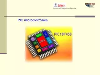
Background: PIC • Peripheral Interface Controllers (PICs) • Inexpensive microcontroller units (few dollars) that include • Central processing unit • Peripherals: memory, timers, and I/O functions • Provide functionality for multitude of applications (e.g., automobile, consumer electronics, safety/security, telecommunication) • Popular in educational, hobby, and industrial applications
PC-based data acquisition and control (DAC) boards High-end DAC boards (e.g., Quanser’s MultiQ3, National Instruments, etc.) Advanced hardware capabilities and sophisticated software environment Drawback: cost! (high hundreds to few thousand dollars) Digital I/Os 8 Analog Inputs 8 Encoder Signals Terminal Board 8 Analog Outputs MultiQ3 ISA DAC Board Motivation—I
Data Acquisition and Control (DAC) Boards Low-end DAC boards Relatively low cost Drawback: use proprietary software DAC boards supported by Matlab Costly and usually include additional hardware features that may not be fully used (e.g., high sampling rates and high resolution analog to digital converter) Motivation—II
Create a Matlab DAC toolbox for PIC microcontrollers Exploit serial communication capability of PIC microcontrollers and Matlab software Use icon-based programming environment of Simulink Illustrate the integration of low-cost PIC microcontrollers with Matlab DAC toolbox environment Use the Matlab DAC toolbox to facilitate Automatic generation of proper PIC assembly codes for a variety of sensors and actuators Automatic programming of the PIC microcontroller Data communication between the PIC microcontroller and Matlab Goals
Prior Research • Basic Stamp 2 (BS2) microcontroller to LabVIEW interface by Radcliffe, 2001 • GUI capabilities for PIC microcontroller via a Matlab interface by Lee et al., 2004 • Matlab data acquisition and control toolbox for BS2 microcontroller by Panda et al., 2004 LabVIEW interface with BS2 Matlab DAC for BS2
Hardware Environment • PIC development board consisting of • PIC16F74 microcontroller with a 20MHz crystal oscillator • MAX232 with five 1μF capacitors • DB-9 connector • PIC development board transmits/receives data to/from a PC via MAX232 • PIC-PG2C programmer • Receives power from the PC’s serial port • IC-Prog to download PIC HEX code to the PIC microcontroller PC and PIC development board PIC-PG2C programmer and PIC
Matlab An interactive technical computing software Simulink Matlab’s icon-based programming environment The PIC assembly language A primitive programming language (35 single-word instruction set) A newly developed Simulink library for the PIC microcontroller Automatically produces and downloads the proper PIC assembly code to the microcontroller Allows data communication between the PIC microcontroller and Matlab MPASM IC-Prog Software Environment I
Sample PIC assembly code to Blink an LED ; LED blink __CONFIG _CP_OFF & _WDT_OFF & _HS_OSC & _PWRTE_ON list P=16F74 include "p16f74.inc" temp EQU 20h temp1 EQU 21h temp2 EQU 22h ORG 0x00 GOTO START START BSF STATUS,5 MOVLW 0x00 MOVWF TRISB CLRF PORTB BEGIN BCF PORTB,0 ;CALL DELAY Aside: PIC Assembly Programming GOTO BEGIN DELAY MOVLW 0x3f MOVWF temp w MOVLW 0xff MOVWF temp2 w1 MOVLW 0xff MOVWF temp1 w2 DECFSZ temp1 GOTO w2 DECFSZ temp2 GOTO w1 DECFSZ temp GOTO w RETURN END
Template.mdl model file Predesigned Simulink model file for interaction with the PIC microcontroller Must be used to design Simulink block diagrams for interaction with the PIC microcontroller TotalCompile has been embedded within the callback parameters Software EnvironmentII Template and model properties
PIC Library Custom library of Simulink blocks for interaction with sensors and actuators connected to the PIC microcontroller Construct a Simulink block diagram by dragging and dropping blocks into the Template model file IOBlock Digital input/output PinStateIn block (8 channels) PinStateOut block (8 channels) Analog input/output ADC block (8 channels) PWM block (2 channels) Software Environment III PIC Library
ADC block Use the 8-bit analog to digital conversion module of the PIC microcontroller Software Environment IV ADC block and parameter
PWM block Use the PWM modules of the PIC microcontroller Produce the required analog voltage output by varying the duty cycle of the PWM signal Software Environment V PWM block and parameter
IOBlock Initiate serial communication between Matlab and the PIC Transmit/receive data between Matlab and the PIC Terminate serial communication between Matlab and the PIC Compute the average sampling period for Simulink block diagram execution Software Environment VI IOBlock and parameters
Integration of Simulink and PIC • Template file is used to construct a Simulink block diagram • Before the start of the Simulink block diagram a Matlab function (TotalCompile) is executed in the following sequence • Declare global variables • Categorize and specify sensor and actuator blocks used in the Simulink diagram • Generate a PIC assembly code • For each sensor/actuator block in the PIC Library the corresponding PIC assembly code has already been created and saved as an m-file • Generate a portion of the IOBlock Matlab code • Program the PIC microcontroller • At the start of the Simulink block diagram the IOBlock is executed first
Programming the PIC microcontroller I • PIC assembly code is generated by TotalCompile • PIC assembly code is converted to PIC HEX code by the MPASM assembler • PIC HEX code is downloaded by IC-Prog via the serial port Flow diagram of programming the PIC microcontroller
Aside: LED Blinker Code from Matlab Toolbox LIST p=16f74 INCLUDE "p16f74.inc" __CONFIG _CP_OFF & _WDT_OFF & _HS_OSC & _PWRTE_ON temp EQU 20h temp1 EQU 21h tempval EQU 22h ORG 0 CLRF STATUS GOTO BootStart BootStart BANKSEL PORTA CLRF PORTA CLRF PORTB CLRF PORTC CLRF PORTD BANKSEL TRISA MOVLW b'11111111' MOVWF TRISA MOVLW b'11111111' MOVWF TRISB MOVLW b'00000000' MOVWF TRISD ADCInitialization BCF STATUS, RP0 MOVLW B'10000001' MOVWF ADCON0 BSF STATUS,RP0 MOVLW b'00000000' MOVWF ADCON1 USARTinitialization BSF STATUS, RP0 MOVLW b'00000001' MOVWF OPTION_REG BCF STATUS, RP0 MOVLW b'10000100' MOVWF INTCON CLRF TMR0 BaudRateSettingsforUSART BSF STATUS, RP0 MOVLW d'10' MOVWF SPBRG MOVLW b'00100100' MOVWF TXSTA BANKSEL RCSTA MOVLW b'10010000' MOVWF RCSTA MOVF RCREG, W MOVF RCREG, W MOVF RCREG, W PWMinitialization BSF T2CON, T2CKPS1 BSF T2CON, TMR2ON BSF STATUS, RP0 MOVLW d'250' MOVWF PR2 BCF TRISC, 1 BCF TRISC, 2 BCF STATUS, RP0 CLRF CCP1CON BSF CCP1CON, CCP1M3 BSF CCP1CON, CCP1M2 CLRF CCP2CON BSF CCP2CON, CCP2M3 BSF CCP2CON, CCP2M2 Main receive1 BCF STATUS, RP0 BCF STATUS, RP1 BTFSS PIR1,RCIF GOTO receive1 MOVF RCREG,W MOVWF tempval compare1 BTFSS tempval,0 GOTO skp1 BSF PORTD, 1 GOTO jmp1 skp1 BCF PORTD, 1 jmp1 NOP GOTO Main END
Illustrative Example–I • Position control of a DC motor is performed to show the efficacy of Matlab data acquisition and control toolbox • The testbed has a DC motor, a continuous rotation potentiometer, and a power module Hardware layer schematic
Illustrative Example–II • A PID controller is used for position control of the DC motor • ADC_Pot block for the analog output of the potentiometer • PWM_Motor block for the analog input to the motor Simulink block diagram
Illustrative Example–III • Experimental setup for the DC motor angular position • PID controller (KP=1.43, KI=1.97, and KD=0.5) • Simulink’s ODE4 (Runge-Kutta) algorithm with a sampling period of 0.13 second • Experimental response of the DC motor angular position • An average 2% settling time of 5.9 seconds and a percentage overshoot of 18.25% DC motor angular position tracking response
Developed a low-cost Matlab Data Acquisition and Control Toolbox for PIC microcontrollers by exploiting Matlab and Simulink Serial communication capabilities of Matlab and PIC Data Acquisition and Control Toolbox designed using our framework allows the user to focus on Hardware-in-the-loop implementation Experimental validation Industry-style rapid control prototyping Our framework allows the use of a microcontroller as a low-cost data acquisition and control board Conclusion