Sequential CPU Implementation
Sequential CPU Implementation. Suggested Reading. - Chap 4.3. Byte. 0. 1. 2. 3. 4. 5. nop. 0. 0. addl. 6. 0. halt. 1. 0. subl. 6. 1. rrmovl rA , rB. 2. 0. rA. rB. andl. 6. 2. irmovl V , rB. 3. 0. 8. rB. V. xorl. 6. 3. rmmovl rA , D ( rB ). 4. 0. rA.

Sequential CPU Implementation
E N D
Presentation Transcript
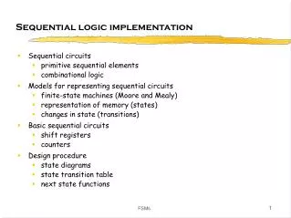
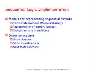
Sequential CPU Implementation
Suggested Reading • - Chap 4.3
Byte 0 1 2 3 4 5 nop 0 0 addl 6 0 halt 1 0 subl 6 1 rrmovl rA, rB 2 0 rA rB andl 6 2 irmovl V, rB 3 0 8 rB V xorl 6 3 rmmovl rA, D(rB) 4 0 rA rB D jmp 7 0 mrmovl D(rB), rA 5 0 rA rB D jle 7 1 OPl rA, rB 6 fn rA rB jl 7 2 jXX Dest 7 fn Dest je 7 3 call Dest 8 0 Dest jne 7 4 ret 9 0 jge 7 5 pushl rA A 0 rA 8 jg 7 6 popl rA B 0 rA 8 Y86 Instruction Set P259
valA Register file srcA A valW W dstW valB srcB B Clock fun A MUX 0 A L U = B 1 Clock Building Blocks P278,P279,P280 • Combinational Logic • Compute Boolean functions of inputs • Continuously respond to input changes • Operate on data and implement control • Storage Elements • Store bits • Addressable memories • Non-addressable registers • Loaded only as clock rises
Hardware Control Language • Very simple hardware description language • Can only express limited aspects of hardware operation • Parts we want to explore and modify • Data Types • bool: Boolean • a, b, c, … • int: words • A, B, C, … • Does not specify word size---bytes, 32-bit words, … • Statements • bool a = bool-expr ; • int A = int-expr ;
HCL Operations • Classify by type of value returned • Boolean Expressions • Logic Operations • a && b, a || b, !a • Word Comparisons • A == B, A != B, A < B, A <= B, A >= B, A > B • Set Membership • A in { B, C, D } • Same as A == B || A == C || A == D • Word Expressions • Case expressions • [ a : A; b : B; c : C ] • Evaluate test expressions a, b, c, … in sequence • Return word expression A, B, C, … for first successful test
4.3.1Instruction Execution Stages P281 • Fetch • Read instruction from instruction memory • Decode • Read program registers • Execute • Compute value or address • Memory • Read or write data • Write Back • Write program registers • PC • Update program counter
Optional Optional D icode 5 0 rA rB ifun rA rB valC Instruction Decoding • Instruction Format • Instruction byte icode:ifun • Optional register byte rA:rB • Optional constant word valC
Fetch Read 2 bytes Decode Read operand registers Execute Perform operation Set condition codes Memory Do nothing Write back Update register PC Update Increment PC by 2 OPl rA, rB 6 fn rA rB Figure 4.16 P283Executing Arith./Logical Operation
Fetch icode:ifun M1[PC] Read instruction byte rA:rB M1[PC+1] Read register byte valP PC+2 Compute next PC Decode valA R[rA] Read operand A valB R[rB] Read operand B Execute valE valB OP valA Perform ALU operation Set CC Set condition code register Memory Write back R[rB] valE Write back result PC update PC valP Update PC Stage Computation: Arith/Log. OpsP283 Figure 4.16 OPl rA, rB • Formulate instruction execution as sequence of simple steps • Use same general form for all instructions M1[PC] 表示从PC开始的内存中读取一个字节的数据。
Fetch Read 2 bytes Decode Read operand register rA Execute Do nothing Memory Do nothing Write back Update register PC Update Increment PC by 2 rrmovl rA, rB 2 0 rA rB Executing rrmovl
Fetch icode:ifun M1[PC] Read instruction byte rA:rB M1[PC+1] Read register byte valP PC+2 Compute next PC Decode valA R[rA] Read operand A Execute valE 0 + valA Perform ALU operation *valE Memory Write back R[rB] valE Write back result PC update PC valP Update PC Stage Computation:rrmovlP283 Figure 4.16 rrmovl rA, rB • Formulate instruction execution as sequence of simple steps • Use same general form for all instructions
Fetch Read 6 bytes Decode Do nothing Execute Do nothing Memory Do nothing Write back Update register PC Update Increment PC by 6 8 rB 3 0 irmovl V, rB V Executing irmovl
Fetch icode:ifun M1[PC] Read instruction byte rA:rB M1[PC+1] Read register byte valC M4[PC+2] Read constant value valP PC+6 Compute next PC Decode Execute valE 0 + valC Perform ALU operation Memory Write back R[rB] valE Write back result PC update PC valP Update PC Stage Computation:irmovlP283 Figure 4.16 irmovl rA, rB • Formulate instruction execution as sequence of simple steps • Use same general form for all instructions
Fetch Read 6 bytes Decode Read operand registers Execute Compute effective address Memory Write to memory Write back Do nothing PC Update Increment PC by 6 rA rB 4 0 rmmovl rA, D(rB) D Figure 4.17 P283Executing rmmovl
Fetch icode:ifun M1[PC] Read instruction byte rA:rB M1[PC+1] Read register byte valC M4[PC+2] Read displacement D valP PC+6 Compute next PC Decode valA R[rA] Read operand A valB R[rB] Read operand B Execute valE valB + valC Compute effective address (sum of the displacement and the base register value) Memory M4[valE] valA Write value to memory Write back PC update PC valP Update PC Stage Computation: rmmovlP283Figure 4.17 rmmovl rA, D(rB) • Use ALU for address computation
Fetch Read 6 bytes Decode Read operand registers rB Execute Compute effective address Memory Read from memory Write back Update register rA PC Update Increment PC by 6 rA rB 5 0 mrmovl D(rB),rA D Executing mrmovl
Fetch icode:ifun M1[PC] Read instruction byte rA:rB M1[PC+1] Read register byte valC M4[PC+2] Read displacement D valP PC+6 Compute next PC Decode valB R[rB] Read operand B Execute valE valB + valC Compute effective address Memory valM M4[valE] Read data from memory Write back R[rA] valM Update register rA PC update PC valP Update PC Stage Computation: mrmovlP283 Figure 4.17 mrmovl D(rB) ,rA • Use ALU for address computation
Fetch Read 2 bytes Decode Read stack pointer and rA Execute Decrement stack pointer by 4 Memory StorevalA at the address ofnew stack pointer Write back Update stack pointer PC Update Increment PC by 2 pushl rA a rA 0 8 Figure 4.18 P284Executing pushl
Fetch icode:ifun M1[PC] Read instruction byte rA:rB M1[PC+1] Read register byte valP PC+2 Compute next PC Decode valA R[rA] Read valA valB R [%esp] Read stack pointer Execute valE valB + (-4) Decrement stack pointer Memory M4[valE] valA Store to stack Write back R[%esp] valE Update stack pointer *在write back之前实际上写入的元素在堆栈外。 PC update PC valP Update PC Stage Computation: pushl P284Figure 4.18 pushl rA • Use ALU to Decrement stack pointer
Fetch Read 2 bytes Decode Read stack pointer Execute Increment stack pointer by 4 Memory Read from old stack pointer Write back Update stack pointer Write result to register PC Update Increment PC by 2 popl rA b rA 0 8 Executing popl
Fetch icode:ifun M1[PC] Read instruction byte rA:rB M1[PC+1] Read register byte valP PC+2 Compute next PC Decode valA R[%esp] Read stack pointer valB R [%esp] Read stack pointer Execute valE valB + 4 Increment stack pointer Memory valM M4[valA] Read from stack Write back R[%esp] valE Update stack pointer R[rA] valM Write back result PC update PC valP Update PC Stage Computation: poplP284 Figure 4.18 popl rA • Use ALU to increment stack pointer • Must update two registers • Popped value • New stack pointer 在写回阶段要写两个寄存器,这两个写是有先后次序的。必须按照上面的方法进行, 因为rA可能就是%esp。具体见书P270 Practice Problem 4.5.
Fetch Read 5 bytes Increment PC by 5 Decode Do nothing Execute Determine whether to take branch based on jump condition and condition codes Memory Do nothing Write back Do nothing PC Update Set PC to Dest if branch taken or to incremented PC if not branch jXX Dest Dest Not taken fall thru: target: Taken 7 XX XX fn XX XX Figure 4.19 P284Executing Jumps
Fetch icode:ifun M1[PC] Read instruction byte valC M4[PC+1] Read destination address valP PC+5 Fall through address Decode Execute Bch Cond(CC,ifun) Take branch? Memory Write back PC update PC Bch ? valC : valP Update PC Stage Computation: JumpsP284 Figure 4.19 jXX Dest • Compute both addresses • Choose based on setting of condition codes and branch condition
Fetch Read 5 bytes Increment PC by 5 Decode Read stack pointer Execute Decrement stack pointer by 4 Memory Write incremented PC to new value of stack pointer Write back Update stack pointer PC Update Set PC to Dest call Dest Dest return: target: 8 XX XX 0 XX XX Executing call
Fetch icode:ifun M1[PC] Read instruction byte valC M4[PC+1] Read destination address valP PC+5 Compute return point Decode valB R[%esp] Read stack pointer Execute valE valB + –4 Decrement stack pointer Memory M4[valE] valP Write return value on stack Write back R[%esp] valE Update stack pointer PC update PC valC Set PC to destination Stage Computation: callP284 Figure 4.19 call Dest • Use ALU to decrement stack pointer • Store incremented PC
Fetch Read 1 byte Decode Read stack pointer Execute Increment stack pointer by 4 Memory Read return address from old stack pointer Write back Update stack pointer PC Update Set PC to return address 9 XX 0 XX Executing ret ret return:
Fetch icode:ifun M1[PC] Read instruction byte Decode valA R[%esp] Read operand stack pointer valB R[%esp] Read operand stack pointer Execute valE valB + 4 Increment stack pointer Memory valM M4[valA] Read return address Write back R[%esp] valE Update stack pointer PC update PC valM Set PC to return address Stage Computation: retP284 Figure 4.19 ret • Use ALU to increment stack pointer • Read return address from memory
Computation StepsFigure 4.16 P285 OPl rA, rB • All instructions follow same general pattern • Differ in what gets computed on each step Fetch icode,ifun icode:ifun M1[PC] Read instruction byte rA,rB rA:rB M1[PC+1] Read register byte valC [Read constant word] valP valP PC+2 Compute next PC Decode valA, srcA valA R[rA] Read operand A valB, srcB valB R[rB] Read operand B Execute valE valE valB OP valA Perform ALU operation Cond code Set CC Set condition code register Memory valM [Memory read/write] Write back dstE R[rB] valE Write back ALU result dstM [Write back memory result] PC update PC PC valP Update PC
Computation StepsFigure 4.19 P284 call Dest • All instructions follow same general pattern • Differ in what gets computed on each step Fetch icode,ifun icode:ifun M1[PC] Read instruction byte rA,rB [Read register byte] valC valC M4[PC+1] Read constant word valP valP PC+5 Compute next PC Decode valA, srcA [Read operand A] valB, srcB valB R[%esp] Read operand B Execute valE valE valB + –4 Perform ALU operation Cond code [Set condition code reg.] Memory valM M4[valE] valP [Memory read/write] Write back dstE R[%esp] valE [Write back ALU result] dstM Write back memory result PC update PC PC valC Update PC
Fetch icode Instruction code ifun Instruction function rA Instr. Register A rB Instr. Register B valC Instruction constant valP Incremented PC Decode § Write back valA Register value A valB Register value B Execute valE ALU result Bch Branch flag Memory valM Value from memory Computed Values
4.3.2, 4.3.3, 4.3.4SEQ Operation • State • Program counter register (PC) • Condition code register (CC) • Register File • Memories • Access same memory space • Data: for reading/writing program data • Instruction: for reading instructions All updated as clock rises • Combinational Logic • ALU • Control logic • Memory reads • Instruction memory • Register file • Data memory
Figure 4.23 P297 SEQ Operation #2 (point 1) • state set according to second irmovl instruction • combinational logic starting to react to state changes
SEQ Operation #3 (point 2) • state set according to second irmovl instruction • combinational logic generates results for addl instruction
SEQ Operation #4 (point 3) • state set according to addl instruction • combinational logic starting to react to state changes
SEQ Operation #5 (point 4) • state set according to addl instruction • combinational logic generates results for je instruction
SEQ Semantics • Achieve the same effect as a sequential execution of the assignment shown in the tables of Figures 4.16 to 4.19 • Though all of the state updates occur simultaneously at the clock rises to the next cycle. • A problem: popl %esp need to sequentially write two registers. So the register file control logic must process it. • Principle: never needs to read back the state updated by an instruction in order to complete the processing of this instruction (P295) • If so, the update must happen in the instruction cycle • E.g. pushl semantics • E.g. no one instruction need to both set and then read the condition codes.
Exercise (2010.4.7) • See page 282 codes, modified as below. • 1 irmovl $-9, %edx • 2 irmovl $9, %ebx • 3 addl %edx, %ebx • Question: • Write the binary code of these three instructions, to be note to have the address value, start from 0x000; • Trace the generic form of addl instruction implementation, and the specific execution of this instruction. Also give the CC value after addl execution.
What we will discuss today? • The implementation of a sequential CPU ---- SEQ • Every Instruction finished in one cycle. • Instruction executes in sequential • No two instruction execute in parallel or overlap • An revised version of SEQ ---- SEQ+ • Modify the PC Update stage of SEQ • to show the difference between ISA and implementation
newPC SEQ Hardware Structure Figure 4.20 P292 PC valE , valM Write back valM • Stages • Fetch • Read instruction from memory • Decode • Read program registers • Execute • Compute value or address • Memory • Read or write data • Write Back • Write program registers • PC • Update program counter • Instruction Flow • Read instruction at address specified by PC • Process through stages • Update program counter Data Data Memory memory memory Addr , Data valE CC CC ALU ALU Execute Bch aluA , aluB valA , valB srcA , srcB Decode A A B B dstA , dstB M M Register Register Register Register file file file file E E icode , ifun valP rA , rB valC Instruction PC Instruction PC memory increment Fetch memory increment PC
Difference between semantics and implementation • ISA • Every stage may update some states, these updates occur sequentially • SEQ • All the state update operations occur simultaneously at clock rising (except memory and CC)
SEQ HardwareFigure 4.21 P293 • Key • Blue boxes: predesigned hardware blocks • E.g., memories, ALU • Gray boxes: control logic • Describe in HCL • White ovals (椭圆): labels for signals • Thick lines: 32-bit word values • Thin lines: 4-8 bit values • Dotted lines: 1-bit values
Fetch Logic Figure 4.25 P299 • Predefined Blocks • PC: Register containing PC • Instruction memory: Read 6 bytes (PC to PC+5) • Split: Divide instruction byte into icode and ifun • Align: Get fields for rA, rB, and valC
Fetch Logic • Control Logic • Instr. Valid: Is this instruction valid? • Need regids: Does this instruction have a register bytes? • Need valC: Does this instruction have a constant word?
Fetch Control LogicP300 bool need_regids = icode in { IRRMOVL, IOPL, IPUSHL, IPOPL, IIRMOVL, IRMMOVL, IMRMOVL }; bool instr_valid = icode in { INOP, IHALT, IRRMOVL, IIRMOVL, IRMMOVL, IMRMOVL, IOPL, IJXX, ICALL, IRET, IPUSHL, IPOPL };
Decode & Write-Back Logic Figure 4.26 P300 • Register File • Read ports A, B • Write ports E, M • Addresses are register IDs or 8 (no access) Control Logic • srcA, srcB: read port addresses • dstA, dstB: write port addresses
OPl rA, rB Decode valA R[rA] Read operand A rmmovl rA, D(rB) Decode valA R[rA] Read operand A popl rA Decode valA R[%esp] Read stack pointer jXX Dest Decode No operand call Dest Decode No operand ret Decode valA R[%esp] Read stack pointer A SourceP301 int srcA = [ icode in { IRRMOVL, IRMMOVL, IOPL, IPUSHL } : rA; icode in { IPOPL, IRET } : RESP; 1 : RNONE; # Don't need register ];
OPl rA, rB Write-back R[rB] valE Write back result rmmovl rA, D(rB) Write-back None popl rA Write-back R[%esp] valE Update stack pointer jXX Dest Write-back None call Dest Write-back R[%esp] valE Update stack pointer ret Write-back R[%esp] valE Update stack pointer E DestinationP301 int dstE = [ icode in { IRRMOVL, IIRMOVL, IOPL} : rB; icode in { IPUSHL, IPOPL, ICALL, IRET } : RESP; 1 : RNONE; # Don't need register ];