
Modulation Synthesis
E N D
Presentation Transcript
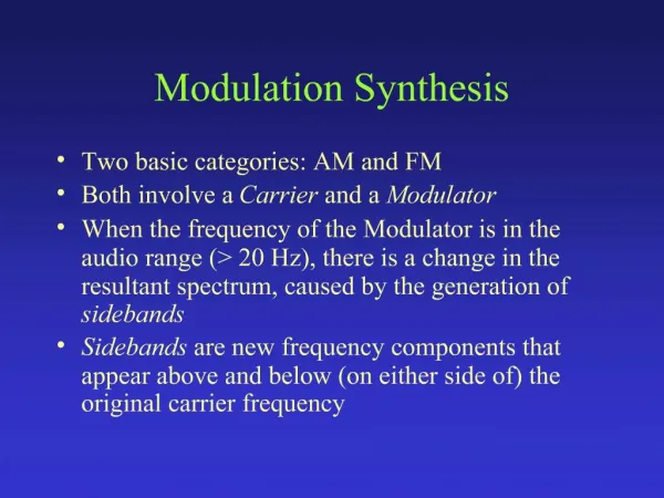
1. Modulation Synthesis Two basic categories: AM and FM
Both involve a Carrier and a Modulator
When the frequency of the Modulator is in the audio range (> 20 Hz), there is a change in the resultant spectrum, caused by the generation of sidebands
Sidebands are new frequency components that appear above and below (on either side of) the original carrier frequency
2. Amplitude Modulation When the frequency of the carrier (Fc) and modulator (Fm) are both in the audio range, sidebands appear at Fc +/- Fm
The spectrum (S) of AM is:
S = Fc, (Fc + Fm), (Fc � Fm)
3. Implementing Simple AM
4. AM Notes Amplitude of Carrier frequency component does not depend on Index (I)
Amplitude of sidebands is I/2 * amplitude of Carrier frequency component
N.B.: If additional frequency components are present in either the Modulator or the Carrier wave, additional sidebands will be generated at corresponding positions
5. Ring Modulation Spectrum identical to that of AM, but Carrier frequency component eliminated
S = Fc + Fm, Fc - Fm
Implementation is actually easier than AM
Ring Modulation results from simply multiplying two audio signals together
Carrier, Modulator labels are arbitrary
6. Implementing Ring Modulation
7. Frequency Modulation Like AM, a Carrier, a Modulator, and Index
Instead of modulating the amplitude of the carrier, however, we modulate its frequency
Classic FM formula:
8. Classic FM Implementation The Modulator causes the basic frequency of the Carrier (C) to deviate periodically, at the frequency of the Modulator (M)
The amount of deviation (D) in C is determined by the Modulator amplitude
In FM, by definition, I = D/M
And I is approximately = N sidebands
Hence, the Modulator amplitude (D) is typically set to I * M
9. Spectrum of FM Sidebands appear on either side of the Carrier Frequency (Fc), at intervals of the Modulator frequency (Fm)
The Index of Modulation determines N - the approximate number of pairs of significant sidebands (really, N tends to be about I+2)
The ratio of Fc/Fm determines the nature of the spectrum
When Fc/Fm is an integer ratio, the spectrum will be harmonic
When Fc/Fm is a non-integer ratio, inharmonic spectra result
10. FM Sideband Generation Negative frequency components �wrap� around 0 Hz, becoming positive frequency components with inverted phase
If negative �wrapped� components coincide with normal components, they will tend to cancel each other out
11. John Chowning�s Rules When C/M = N1/N2 and N1 and N2 are integers with no common factors:
Carrier always the N1th harmonic
If N2 = 1, spectrum has all harmonics and fundamental at modulating Hz (M)
If N2 an even number, only odd harmonics
If N2 = 3, every 3rd harmonic is missing
12. Sideband Amplitudes in FM Sideband amplitudes vary according to the Modulation Index (I), but not directly.
They may be predicted using Bessel functions of 1st kind and kth order, where k = number of the sideband:
13. Assignment Read Dodge: Chapter 4 & 5 (pp: 115-139)
Read Boulanger: Chapter 12 (Pinkston)
Study FM instrument in Primer Sample Orchestra 3
Study instruments 1201 & 1202 in the Pinkston FM chapter