Modulation
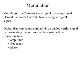
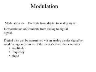
Modulation. Definitions. Amplitude: “Size” Frequency: “Rate of occurrence” Phase: “Position or interval within a cycle” Modulation: “To vary amplitude, frequency, or phase”. “Magical”. “Carrier”. Voltage or Current. Pure Sine Wave (146 MHz, no info). NOT These. Time or Distance.

Modulation
E N D
Presentation Transcript
Definitions • Amplitude: “Size” • Frequency: “Rate of occurrence” • Phase: “Position or interval within a cycle” • Modulation: “To vary amplitude, frequency, or phase”
“Magical” “Carrier” Voltage or Current Pure Sine Wave (146 MHz, no info) NOT These Time or Distance
Voltage or Current HF and VHF Carriers Slow (HF, 80 m, 3 MHz) Fast (VHF, 2 m, 144 MHz) Time or Distance
“Carrier” Carrier/CW/AM Modulator or speech AM CW or OOK (BW=150 Hz)
Single Audio Tone AM vs. FM BWFM = 5 to 15 KHz
AM SSB USB LSB DSB Sidebands 3 KHz Note break in axis 28 MHz
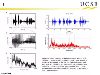
Compression 2. Single Tone Test Waveform: Just a pure RF sinewave offset from carrier by audio tone frequency!! “Splatter” 1. Two Tone Test Waveform SSB (BW = 3 KHz)Long Distance or Weak Signal 3. This is how SSB speech sounds (tuned, AM detection, untuned) Sound clip: http://www.hamuniverse.com/ssbinformation.html Photo: http://users.tpg.com.au/users/ldbutler/Intermodulation.htm
Amateur TV • Analog fast-scan NTSC • Widest BW (6 MHz) • 440 MHz , 75 cm
Modulation Video Demos http://hamelmer.com/Videos.html
Fldigi WinPack FSK PSK Digital / Data Modes Audio IN/OUT USB TNC/Sound Card
Digital / Data Modes • 219 to 220 MHz, also others • Many different “flavors” • “parity bit” extra bit detects errors • BER = Bit Error Rate • GPS can provide APRS
PSK31 • Low Data Rate (Keyboard) • continuous whistle with a slight warble Sound files from http://www.kb9ukd.com/digital/
MFSK • Shifts Audio Frequency between a number of different tones • Low data rate 64 bps • Sounds like a crazy bird Sound files from http://www.kb9ukd.com/digital/
Packet • “High” Data Rate • Checksum • Header (Destination Call Sign) • Automatic Repeat if error detected • How it sounds: Sound files from http://www.kb9ukd.com/digital/
Satellites SO-50 AO-27 Mode V/U (J) FM Voice Uplink: 145.8500 MHz FM (2 m) Downlink: 436.7950 MHz FM (75 cm)
Satellite Info • 30+ operating satellites, including ISS • Any ham with privileges that allow transmitting on uplink frequency • Use minimum power necessary (as always) • Member contacted ham in England • U/V means UHF uplink, VHF downlink • V/U VHF up, UHF down
Satellite Orbits few hundred miles up 22,237 miles up Drawing http://www.gma.org/surfing/sats.html
Doppler Shift • LEO – Low Earth Orbit • Vs. Geostationary • 17,000 mph! • Start by tuning receive freq HIGH by 15 KHz • End by tuning receive freq LOW by 15 KHz Sound file http://www.exploratorium.com
Satellite Location • Get Pass Info from satellite tracking program, or • Get Pass Info from web (see screenshot above)
Satellite operation • Show up at correct time! • Steer beam antennas, tune radios for Doppler • Spin Fading due to rotation of satellite and antennas • Very short voice contacts • Callsign and GridSquare (WA1QKT FN32) • FM Packet commonly used digital mode
Single-conversion superheterodyne receiver for CW/SSB CW/SSB Receiver 28 MHz CW/SSB RF signals Product Detector 455 KHz BP filtering for selectivity 500 Hz 455.5 KHz 28.455 MHz
FM Receiver (VHF/UHF) 146 MHz FM RF signals Limiter Eliminates Any trace of AM Discriminator FM to Audio RF preamplifier Increases sensitivity 1 KHz 10.7 MHz 135.3 MHz
CW Transmitter Oscillator
Other Equipment • Transverter – Transmitter frequency converter • Example: 28 MHz up to 222 MHz • RF Power Amplifier – 5W up to 25 Watts (see satellite setup)
SWR • Standing Wave Ratio • Zload = Zo (Feedline characteristic impedance)? • If Zload = Zline , SWR = 1, else SWR > 1 • SWR > 1:1 Due to Reflections from load, and Constructive and Destructive interference “Standing Waves”
Acceptable “SWR”? • 1:1 is perfect match • 2:1 is fairly good, but transmitter may start to reduce power output • 4:1 is poor, may stress parts, some power lost as HEAT in feedline, and transmitter will reduce power output
Antenna Tuner and SWR Meter Measures Impedance Ratio Impedance Transformer
SWR Meter • Forward, adjust Sensitivity to “SET” (Transmitting) • Reverse, read SWR (Transmitting)
Note that “SWR Meter”, when used with Antenna Tuner, Doesn’t actually measure SWR on feedline Antenna Tuner Action Measures Impedance Ratio Between Zload and design Z = 50 Ohms “SWR =1:1” means Zload = 50 Ohms “Impedance Transformer” High SWR on feedline is still present and is usually OK Low SWR Here Transmitter is Happy, because it can deliver power to antenna system!
Dummy Load Use to prevent Radiation when Testing Transmitter (instead of using Antenna)
Handheld Radios (HTs) Generally safe as is Low Battery Voltage, Enclosed Low Power gives low RF exposure Low Power gives low antenna voltage (16Vrms)
RF Exposure • Non-Ionizing radiation • Hazard is said to be Tissue Heating • Microwaves – eyes most vulnerable
Thresholds for RF Evaluation Re-evaluate the station whenever an item of equipment is changed
To Reduce RF exposure: • Relocate antennas • Reduce Power • Change frequency band • Change antenna radiation pattern • Change antenna heading
Electrical HazardsP=IV=IE 1. High V, Low I 2. Low V, High I 3. High V, High I
Human Body Model A pair of copper wires was connected to a 120V wall plug. The extreme danger of this was explained and then a hotdog was used to short-circuit the wires. The hotdog was cooked and then later eaten by a participant. DO NOT TRY THIS AT HOME!
Shock Protection • 3-wire cords with safety ground pin • Common ground for all equipment • GFI • Check voltage on large capacitors, discharge if necessary
Lightning Protection Disconnect Antennas Ground Antennas Do NOT operate with external antennas during thunderstorms 8’ ground rods for each tower leg, short and direct connections to tower and each other, no sharp bends Lightning protectors all to common plate