Download
1 / 16
160 likes | 321 Views
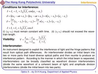
As competition for spectrum intensifies, understanding interference impacts has become crucial for effective spectrum management. This report details a sophisticated approach for analyzing sharing impacts within the 31.5-31.8 GHz frequency band, which involves comparing the characteristics and emissions of fixed and mobile services against existing interference standards. We present simulation results highlighting the interference thresholds that could affect satellite passive sensing operations, offering insights into emitter configurations and providing critical data for regulatory discussions.

E N D
An Approach for Interference Analysis David Furlong Rich Kelley Bill Daniels NESDIS spectrum manager Alion Science and Technology Alion Science and Technology Silver Spring, MD 20910 Suitland, MD 20746 Suitland, MD 20746 David.furlong@noaa.govrichard.kelley@noaa.gov bill.daniels@noaa.gov 01.301.713.2789 x 149 01.301.817.4636 01.301.817.4628
Background Competition for spectrum has never been keener • We share 18 bands1with active services • We “own” 21 exclusively passive bands2 For how long? Commercial sector deploying increasing systems • We will lose spectrum if we can’t analyze sharing impacts and defend what we have Now we have sophisticated tools to perform sharing analyses. We know how to use them. Here’s how, in a specific application 1ITU-R RECOMMENDATION ITU-R RS.515-4, “Frequency bands and bandwidths used for satellite passive sensing” 2International radio regulations 5.340.
Technique applied to a specific application Sharing the 31.5-31.8 GHz band fixed and mobile services and the Earth exploration-satellite service (passive) characteristics from fixed and earth exploration satellite services (FS and EESS) (no known plans by mobile service)
Technique • Assign characteristics to emitters and sensor • Scana region of emitters with the sensor • Examine the output for sensed emission values • Compare results to existing interference standards • Standards for satellite passive sensing are in ITU recommendations on performance and interference criteria 1,2 . 1ITU-R RECOMMENDATION ITU-R RS.1028-2, “Performance criteria for satellite passive remote sensing” 2ITU-R RECOMMENDATION ITU-R RS.1029-2, INTERFERENCE CRITERIA FOR SATELLITE PASSIVE REMOTE SENSING
Characteristics of emitters and sensor • Sensor characteristics are in an ITU recommendation 1 • Conical and cross track sensors • cross track – U.S., Europe, China • conical – Russian federation 1ITU-R RECOMMENDATION ITU-R RS.1861 “Typical technical and operational characteristics of Earth exploration‑satellite service (passive) systems using allocations between 1.4 and 275 GHz”
Characteristics of emitters and sensor Instantaneousfield of view (IFOV)
Characteristics of emitters and sensor • emitter characteristics are sometimes provided by the service • Critical elements of characteristics:
Scan a region of emitters with the sensor emitters are placed every 500 metres in areas of various horizontal extent The smallest area, with 1,089 emitters
Scan a region of emitters with the sensor a passive scanner is “orbited” and periodically scans the area
Compare results to existing standards Recommendation ITU-R RS.1029-2 -permissible interference levels use in sharing studies. in this case the level is −164.24 dBW/300 MHz
Compare results to existing standards Run simulations iteratively adjusting emitter power until interference level is reached ATMS results
Summary results for all simulations and sensors AMSU-A and MTVZA‑OK are more sensitive than the ATMS. The worst case sensitivity is for the AMSU for large areas (large number of emitters) In this case the power density is −51.97 dBW/km2
Summary results for all simulations and sensors • Adjust −51.97 dBW/km2for • polarization loss • gaseous attenuation • antenna side-lobe gain • The limit is −40.62 dBW/km2 (for AMSU-A)
actual deployment advertised1 by Fixed Service a typical emitter would have −18 dBW power Means an emitter density of 0.0055 emitters/km2 Or a large city (3,139 km2) there could be 17 emitters If 2 000 emitters are in the cities1 the deployment density is 0.154 emitters/km2. To meet the interference threshold of -40.62 dBW/km2 each emitter could have only −32.5 dBW of power…Fixed service advertises -18 dBW/emitter 1ITU-R Working Party 5CREPLY LIAISON STATEMENT TO WORKING PARTY 7CINFORMATION REGARDING STUDIES UNDER QUESTION ITU-R 232-1/7
Results and conclusion • deployment density provided by the fixed service would not be compatible with the sensor. • (compatible configurations would have an average of 17 or fewer emitters per city at typical power levels) • These results were presented during ITU-R meetings in September 20111 1 ITU-R SG-07 Draft new Report IUT-R RS.[31.5 GHZ SHARE] - Sharing the 31.5-31.8 GHz band by the fixed and mobile services and the Earth exploration -satellite service (passive)