Download
1 / 15
150 likes | 256 Views
Explore the history and innovation of artificial horses with a focus on realistic representation in compression mode. Learn about fuel-air models for engine cycles and the thermodynamic strategies for combustion to achieve maximum temperature. This comprehensive book by Professor P.M.V. Subbarao, a mechanical engineering expert, delves into accurate representations of constituents and isotropic processes in Otto cycles.

E N D
Fuel-Air Modeling of IC Engine Cycles - 1 P M V Subbarao Professor Mechanical Engineering Department State of the Art Modeling of Artificial Horses.….
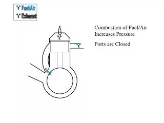
The Important part of Cycle is Executed in CM Mode More realistic representation of Compression???
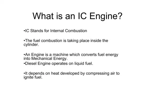
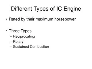
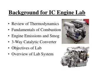
Fuel-Air Models for Engine Cycles • Fuel-air analysis is more realistic analysis when compared to Air-standard cycle analysis. • An accurate representation of constituents of working fluid is considered. • More accurate models are used for properties of each constituents.
Fuel – Air Otto Cycle Air+Fuel vapour +Residual gas TC Products of Combustion Products of Combustion BC Compression Process Const volume combustion Process Expansion Process Blow down of waste Products of combustion
Fuel –Air Otto Cycle • 1—2 Isentropic compression of a mixture of air, fuel vapour and residual gas without change in chemical composition. • 2—3 Complete combustion at constant volume, without heat loss, with burned gases in chemical equilibrium. • 3—4 Isentropic expansion of the burned gases which remain in chemical equilibrium. • 4—5 Ideal adiabatic blow down.
Isentropic Compression Process For a infinitesimal compression process: Use appropriate EoS: Mass averaged properties for an ideal gas mixture:
g cp cv
True Phenomenological Model for Isentropic Compression Let the mixture is modeled as:
First Order Models for Variable Specific Heats ap = 0.9718 – 1.1 kJ/kg.K bv = 0.685 – 0.823 kJ/kg.K k1 = 1.32610-4 – 3.39510-4 kJ/kg.K2
Isentropic Compression model with variable properties • For compression from 1 to 2:
Phenomenological Modeling of Combustion • Engineering Objective of Combustion: • To Create Maximum Possible Temperature through conversion of microscopic potential energy into microscopic kinetic energy. Thermodynamic Strategy for conversion: Constant volume combustion Constant pressure combustion