Download
1 / 12
120 likes | 140 Views
This is an update on the DCM II system prototype, including its current status, chain test progress, and schedule for production.

E N D
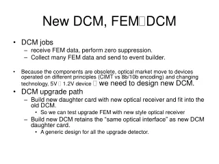
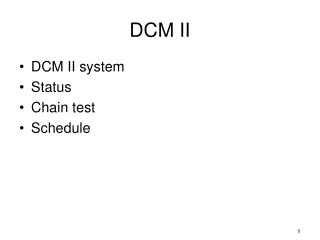
DCM II • DCM II system • Status • Chain test • Schedule
DCM II system diagram Custom Backplane BUSY DOWNLOAD READBACK DATA L1 controller Partitioner III DCM II DCM II DCM II GTM L1 Download/reback 40Mbytes/sec DCM data link 640 Mbytes/sec DCM II/ JSEB II link 6.4 Gbits/sec. FEM/DCM 16bits/80MHz clock FEM JSEB II JSEB II PC SEB PC < one per partitioner3 > < one per crate > The DCM II system is similar to the DCM – the JSEB II will use PCI express bus (2.5 Gbits/sec/per lane) in PC. The new JSEB will have by-directional optical links.
DCM II Block Diagram ALTERA STRATIX III EP3S150 8 optical links per DCM 5 event buffer Event buffer 320 Mbytes/sec Optics+ De-serializer Zero sup- pression ALTERA STRATIX III EPS150 L1 data MUX 5 event buffer Event buffer Optics+ De-serializer Zero sup- pression receiver buffer Data link in Alignment FEM DCM link 80 MHz 16 bits/word 1.6Gbits/sec 8b/10b encoding method choose Ti’s TLK2501 as de-serializer STRATIX III has (2 Mbits for event data buffer 1 Mbits for processing buffer) 5.4 Mbits for memory 142K logical element old DCM has 1K Logical element per optical link Data processing Event Buffer 640 Mbytes/sec MUX Data link out receiver buffer 5 event buffer Event buffer Optics+ De-serializer Zero sup- pression STRATIX III has (1 Mbits for event data buffer 1.5 Mbits for processing buffer) 5.5 Mbits of memory 142K ( 20K - 60 K) logical element MUX 5 event buffer Event buffer Optics+ De-serializer Zero sup- pression Alignment ALTERA STRATIX III EP3S150
DCM II 3.3V 2.5V JTAG 1.1V 6U X 160 MM size (HBD FEM size) 48V for power input 48V in (Isolated) ( 160 MB/sec) 320MB/sec clock JTAG 8(4 ) FEM fiber inputs L1 data (640MB/sec) 1.1V FPGA boot from PC 8MB per FPGA, 5 FPGA (40 MB/sec download bandwidth) (2-4 sec per board ???) Download (readback) 5V in (control)
INTERFACE MODULE (DCM2_I) 40MB download/readback bandwidth JSEBII Optical Download (readback) 5V in (control)
PICTURE Controller DCM II Backplane + clock fanout
We are about to fabricate the Paritioner 3 Module prototype 1.6 Gbps Link from L1 Waiting for P.O., final modifications (4 traces) and recheck 3.125 Gbps link 1 &2 to JSEB 2
DCM2 status • We are able to boot the FPGA on DCM2 • Power up boards • Controller is fine.. • Able to download/loopback on the downloaded code • Start to test optical inputs.
JSEB II Loopback the data on individual optical links Take data from ATLAS ADC test stand. (65Kbytes per events) ( via JUNGO software) Did not test the interrupt yet. Using ALTERA PCI express core for the PCI express interface (currently running development mode (no EPROM files) Testing final data taking FPGA code.. Should be done very soon.. Colorado group is working on interface with the event builder. Fibers from Partitioner II 4 Lanes PCI express
DCM2 build * Include JSEB II for the crate controllers The build for the final system running at full bandwidth. The ratio between partitioner 3 to DCM is 2 to 1 16 fibers 1 fiber 10 crates, 10 backplanes, 10 clockfanout
Chain test question • Unlike the original DCM, DCM II has a head start on the chain test.. • The FE3 daughter card using the same protocol/format as the DCM2 will be using • The VTX Pixel has been taking data with FE3 daughter for many months (FNAL test beam??) • The strip FEM should follow the same path.. • There is a generic pass through code in place for the FE3 card. • The testing plan on the DCM II will be using either RPC and HBD to test the optical input.. • Some point we will need readout VTX detector. • Yes. We probably will have some problems. • Interaction between FEM, GTM and DCM II. • Some point we will need to produce a data compression code…
Schedule • Normally production run take 6 month.. • 3 month components, 1 month PCB, 1 month assembly, 1 month testing.. • We are not ready yet to make the PCB. But we are ready to order the components. • Money is somewhere between BNL/Columbia/Nevis.. • Can not do anything till account is setup in Nevis. • I asked the distributor to give me an estimated the components delivery leadtime in late February. • Economy is recovering but Manufacture is behind… • The longest components is 52 weeks ( they really don’t know the schedule) • Several TI parts is around 20 weeks + • We have to switch PowerOne part to Delta electronics part • Long delivery time on 48V capacitance. • We are taking steps to reduce the impact from the leadtime issue. • I don’t think we will be get away with min. 3-4 months lead time after account is setup in Nevis.