Download
1 / 20
200 likes | 370 Views
FPGA Based Interfaces for Smart Sensors and Actuators. What is an FPGA?. A F ield- P rogrammable G ate A rray (FPGA) is a digital integrated circuit that can be customized by the designer “in the field” using a H ardware D escription L anguage.

E N D
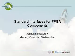
FPGA Based Interfaces for Smart Sensors and Actuators ENGI 5951 – Mechatronics II
What is an FPGA? • A Field-Programmable Gate Array (FPGA) is a digital integrated circuit that can be customized by the designer “in the field” using a Hardware Description Language. • FPGAs contain thousands of components called "logic blocks“ that can be “wired together” through a hierarchy of reconfigurable interconnects. ENGI 5951 – Mechatronics II
What is an FPGA? • Modern FPGAs can have on the order of 200K Logic Cells. A simplified representation of a Logic Cell is shown below. ENGI 5951 – Mechatronics II
Quadrature Decoder/Counter Interface for Optical Encoder: State Machine ENGI 5951 – Mechatronics II
Optical Encoder ENGI 5951 – Mechatronics II
Optical Encoder - Decoding ENGI 5951 – Mechatronics II
Optical Encoder – State Diagram ENGI 5951 – Mechatronics II
Optical Encoder – Edge Detection Circuitry ENGI 5951 – Mechatronics II
Summary of Quadrature Decoding Logic Note: and indicate a rising and falling edge respectively. ENGI 5951 – Mechatronics II
Truth Table Implementation of Quadrature Decoder TABLE enc_dec[3..0].q => dwn_cnt, up_cnt; B"0000" => 0, 0; B"0001" => 0, 1; B"0010" => 1, 0; B"0011" => 0, 0; B"0100" => 1, 0; B"0101" => 0, 0; B"0110" => 0, 0; B"0111" => 0, 1; B"1000" => 0, 1; B"1001" => 0, 0; B"1010" => 0, 0; B"1011" => 1, 0; B"1100" => 0, 0; B"1101" => 1, 0; B"1110" => 0, 1; B"1111" => 0, 0; END TABLE; ENGI 5951 – Mechatronics II
AHDL Implementation of Counter Module IF up_cnt THEN encoder[].d = encoder[].q + 1; ELSE IF dwn_cnt THEN encoder[].d = encoder[].q - 1; ELSE encoder[].d = encoder[].q; END IF; END IF; ENGI 5951 – Mechatronics II
Stepper Motor Controller: Synchronous Counter Design ENGI 5951 – Mechatronics II
Stepper Motor Half-Step Switching Sequences ENGI 5951 – Mechatronics II
Truth Table for Half-Stepping Switching Sequence ENGI 5951 – Mechatronics II
Stepper Motor: Synchronous Counter Design ENGI 5951 – Mechatronics II
Stepper Motor: Synchronous Counter Design Schematic of stepper motor controller ENGI 5951 – Mechatronics II
Pulse-Width Modulation: VHDL/AHDL Programming ENGI 5951 – Mechatronics II
AHDL Implementation of PWM Controller totaltime[].clk = clk; totaltime[].clrn = VCC; totaltime[].prn = VCC; totaltime[].ena = io_space_2 & (add_latch[3..0].q == B"0110") & !write/; totaltime[].d = add_data[]; lowtime[].clk = clk; lowtime[].clrn = VCC; lowtime[].prn = VCC; lowtime[].ena = io_space_2 & (add_latch[3..0].q == B"0111") & !write/; lowtime[].d = add_data[]; ENGI 5951 – Mechatronics II
AHDL Implementation of PWM Controller cntr[].clk = clk; cntr[].clrn = !(cntr[].q == totaltime[].q); cntr[].prn = VCC; cntr[].ena = VCC; cntr[].d = cntr[].q + 1; switch.clk = clk; switch.clrn = VCC; switch.prn = VCC; switch.ena = VCC; pwm_out = switch.q; switch.d = (cntr[].q < lowtime[].q); ENGI 5951 – Mechatronics II
Conclusions • CPLDs are well suited to the implementation of interfaces for smart sensors and actuators. • Incorporating a CPLD that supports In-System Programmability (ISP) into a data acquisition system provides reconfigurable digital I/O that allows the target system to be reprogrammed by the user for a variety of applications without hardware modifications. • This is particularly useful for those applications that require hardware interfaces for several different sensors simultaneously. ENGI 5951 – Mechatronics II