Download
1 / 16
160 likes | 296 Views
Status of 2000 test-beam analysis. Jim Libby on behalf of M. Charles, P. Collins, O.Dortmond, F. Fiedler, C. Parkes, U. Parzefal and F. Teubert. LHCb week VELO meeting 27 th November 2000. Motivation The telescope, detectors, hybrids and irradiation CCE Micron detector

E N D
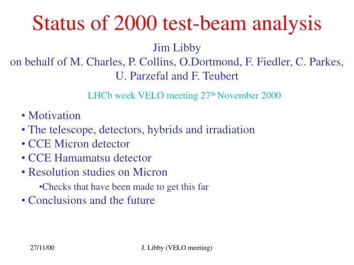
Status of 2000 test-beam analysis Jim Libby on behalf of M. Charles, P. Collins, O.Dortmond, F. Fiedler, C. Parkes, U. Parzefal and F. Teubert LHCb week VELO meeting 27th November 2000 • Motivation • The telescope, detectors, hybrids and irradiation • CCE Micron detector • CCE Hamamatsu detector • Resolution studies on Micron • Checks that have been made to get this far • Conclusions and the future J. Libby (VELO meeting)
Motivation • For TDR study of the cluster finding efficiency and resolution (especially in fine pitch regions) with voltage. • Also as function of: • Radiation dose • Track angle • Detector thickness • p-on-n or n-on-n detectors • Floating strips • Use test beam results themselves or as input to simulation to answer these questions • Parasitic running for much of year and ~2 weeks dedicated running with irradiated test detectors in late August-early September this year J. Libby (VELO meeting)
Telescope • New mechanics for 2000: • detector supports to allow 1 mm positioning • Fridge and cool box (-300 C-100 C on detector) • New black boxes • Scintillators • All from Lausanne J. Libby (VELO meeting)
Hybrids and detectors • Fast station: Hamamatsu R equipped with • 6 SCTA chip hybrid (CERN, Guido) • Required repeater board (Lausanne) • Irradiated 200 m thick Micron detector • equipped with 23 SCTA chip hybrids • One dead chip on non-irradiated side • Irradiated 300 m thick Hamamatsu detector • equipped with 23 SCTA chip hybrids • One chip connected irradiated (left) side • Two chips operational on unirradiated (right) side More details Guido’s presentation from Milan J. Libby (VELO meeting)
Irradiation: Micron • G.Casse, T.Ruf and F.Teubert • Maximum fluence: • 101014 protons/cm2 • Still uncertainty in position of beam with respect to detector • Use beam profile to fix this (F. Teubert) fig. J. Libby (VELO meeting)
Irradiation: Hamamatsu • Maximum fluence: • 4.11014 protons/cm2 • Again knowledge of beam • profile will allow a • more accurate determination of • irradiation position J. Libby (VELO meeting)
SCTA performance and fast station • First step look at un-irradiated detector equipped with SCTA • Plotting the integrated charge vs TDC clear SCTA pulse shape (Paula) fig • Integrated over 5 strips (strip of cluster centre ± 2 either side) • Signal peaks at around 65 • Chris also has measurements of this in which are in agreement • Also measurements of pulse shape and further studies of SCTA possible • Example ‘ballistic loss’ figures • A lot of data (over 1 million events) with SCTA readout J. Libby (VELO meeting)
Micron CCE measurement • Results shown in Milan from Paula figs • Expect 2/3 of charge in 200 m compared to 300 m detector • Appears to be loss of charge compared to fast station even on unirradiated side • Improvements with new alignment gives a 10 % increase • 27 counts compared to 40 expected • 20-25% deficit • Expectation from the Rose collaboration is a 200 m oxygenated detector should be fully depleted at 300 V. • However, some good strips fig J. Libby (VELO meeting)
Micron CCE continued • Possible additional cause of loss due to increased capacitive coupling to back-plane : Al w Normally Cback ~ 0.3 pF/cm and Ccoup~10 pF/cm therefore ratio yields a ~3% loss to back plane. d Cback C_back = (0Si (p/d)) (1+(p/d)f(w/p))-1 where p = pitch (E. Barberis et al NIMA 342 (1994) 90) Backplane • The value of w is low at 8 m for Micron detector • Need to measure capacitances etc detector to Krakow J. Libby (VELO meeting)
Micron CCE continued • Even with this loss of charge signal to noise is good: • 27 signal / 2.5 noise ~ 10 - 11 ( around required level for operation) • CCE measurements now extended over most of Micron detector fig • There are maps at 300 V and 200V figs • Some correlation of ineffiency with radiation: • Particularly clear at 200 V • Still work to do understanding the loss and complete CCE maps • at different voltages • Also hardware question of voltage due to biasing of guard ring J. Libby (VELO meeting)
Hamamatsu CCE • Mat and Uli performing analysis • Mat unirradiated side and Uli irradiated side • Cross--checking each other at present • Plots unirradiated side: • Align • Integrated charge vs TDC • Peak vs voltage • Plots irradiated side • Analysis ongoing update and firming up of results for • Liverpool J. Libby (VELO meeting)
Resolution studies:Fast station • With current telescope including fast station one expects an • extrapolation error of: • 5.5 m at the fast station • 4 m at the test detector • For the fast station this leads to an expectation is 7.5 m for the • 40 m pitch region that has been equipped. (Vic’s studies) • There has been a lot of difficulty in even getting close to • z free • outliers • full telescope alignment • TDC window • The current best resolution at fast station is ~ 9.3 m fig. • There is still some scatter with the residuals plotted against • R on the detector fig • Additional alignment error of 5.5 m J. Libby (VELO meeting)
Resolution studies:Micron • So even with this additional error from the alignment the resolution of the Micron detector has begun to be investigated • Firstly looking at a set of runs (around number 2943) at 300 V on the unirradiated side figs. • Deconvoluting the extrapolation error gives resolution of: • 12.0±1.1m (pitch ~ 40 m) • 17.0±1.1m (pitch ~ 47 m) • 23.0±1.8m (pitch ~ 53 m) • With caveats about charge loss and alignment see later • Now for unirradiated side….. figs • All very preliminary but looks hopeful….. J. Libby (VELO meeting)
Alignment and resolution studies remarks and conclusions • Current alignment procedure: • one detector at a time and use MINUIT to get 6 alignment • parameters then iterate • This seems inadequate to sort out certain problems (e.g. bow tie) • Fix one detector and throw MINUIT at the remaining 86 alignment • parameters not an option…. • Probably a method using matrix inversion is the solution though this • will take time to implement • In the mean time aligning in small regions will allow the • measurement as a function of voltage and radiation to be made • Update at Liverpool J. Libby (VELO meeting)
Remarks on getting this far withCCE and resolution • Checks of geometry of both Hamamatsu and Micron detector have • been made either through observation or confirming with P. Turner • Stereo angles remeasured or checked etc • Angles subtended • Transitions between regions • Then cross checked with software description • No major problems found including bonding errors • Also software algorithms for • noise • common mode correction (Odie ) • clustering • Still track fit to check J. Libby (VELO meeting)
Conclusions and future • A lot of data with fast station to study SCTA • CCE for both irradiated detectors are well underway with interesting preliminary results • Resolution in fast station OK apart from additional alignment error • Micron resolution some promising results and others that require further investigation and of course problems in alignment procedure • Outstanding hardware issues on voltage and capacitances • Updates at Liverpool • Future: provisionally two periods next year in July and September….. J. Libby (VELO meeting)