Download
1 / 5
60 likes | 546 Views
PEUGEOT 206 INSTALLATION 99’— 05’ 206 1.6 TU5JP4 1. Remove the air intake system 1.Remove all parts of the air cleaner,

E N D
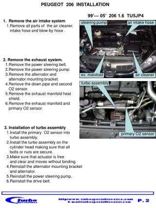
PEUGEOT 206 INSTALLATION 99’— 05’ 206 1.6 TU5JP4 1. Remove the air intake system 1.Remove all parts of the air cleaner, intake hose and blow-by hose . 2. Remove the exhaust system. 1.Remove the power steering belt. 2.Remove the power steering pump. 3.Remove the alternator and alternator mounting bracket. 4.Remove the down pipe and second O2 sensor. 5.Remove the exhaust manifold heat shield. 6.Remove the exhaust manifold and primary O2 sensor. 3. Installation of turbo assembly 1.Install the primary O2 sensor into turbo assembly. 2.Install the turbo assembly on the cylinder head making sure that all bolts or nuts are secure. 3.Make sure that actuator is free and clear and moves without binding. 4.Reinstall the alternator mounting bracket and alternator. 5.Reinstall the power steering pump. 6.Reinstall the drive belt. . steering pump air intake hose Ex ex. manifold air cleaner turbo assembly primary O2 sensor
oil return fitting 4.Installing oil return fitting 1.Remove the oil filter and filter mounting assembly. 2.The oil pressure sending unit is attached to the assembly and needs to be removed from assembly for installation in a new location.. 3.Remove the oil relief O ring oil filter and oil filter mounting adapter from assembly. 4. Install the oil filter mounting adapter into the now exposed oil filter mounting location on the block and install new oil filter included in kit. 5. Install oil relief O ring into oil return fitting assembly included with this kit. 6. Install oil return assembly to oil relief hole using one bolt . oil return fitting assembly 5. Install the oil return hose. 1.Install the oil return hose between turbo oil outlet and oil return fitting. 2.Using the hose clamps included in the kit, secure the oil return hose. 6. Installing of oil supply system Locate plug in front of head as shown in in photo. Remove plug and proceed. 1.Install (T) fitting adaptor into engine head. 2.Install brass (T) connector into (T) fitting adapter and install oil pressure sending unit into (T) fitting. 3.Install oil line fitting in the side of the (T) fitting. 4.Connect stainless oil line to oil line fitting. 5.Bring oil line around to turbo and connect to oil inlet of turbo. oil return hose (T) fitting adapter oil sending (T) fitting to turbo
down pipe 7. Installation of the down pipe 1.Reinstall second O2 sensor in the down pipe. 2.Install the down pipe with gasket to the turbo exhaust outlet. 3.Connect down pipe to exhaust system with gasket. second O2 sensor 8. Installation of water cooling system 1. install the new heater hose included in the kit. between water inlet and water (T) fitting the other end to heater. 2.Locate the heater water outlet hose, cut in half in an easy to reach location Insert the (T) fitting supplied into each half of the hose and secure with hose clamps supplied. 3.Connect the stainless water lines supplied to the (T) fittings and then feed both lines to the turbo. connect the water lines to either of the water connections of the turbo. . to heater to turbo (T) fitting from engine
9. Installing the intercooler system 1. Installing the intercooler first fit the charge piping to compressor outlet and around to intercooler inlet. Then locate position of intercooler mounting to correspond with charge piping. 2.See photograph to locate chassis position to mount intercooler. intercooler fix chassis 10. Install and connect charge piping 1.Refer to photos and drawing for flow layout. 2.Note corresponding numbers on charge piping. A. Flow of charge air is in the direction of the arrow on the charge pipes. 3. Install blow off valve on intercooler as shown. A. There is an adjustment screw on top of B.O.V. for sooner or later release of pressure. IP201 2 to throttle from turbo BOV 1 11. Installation of air intake system 1.Install one end of the air intake hose to the compressor inlet, and the other end to the air filter. 2.Install the blow-by hose to the quick connector and to the air intake hose. blow-by hose air filter check valve air intake hose
IP201 12. Fuel system installation 1.If you are using the 2 extra injector fuel system mount the Ip201 interface between charge pipe and throttle body. A Disconnect the factory fuel rail from the nipple and install rail adapter. . B. Using the stainless fuel line included connect one end of the Ip201 injector interface and the other end to the fuel rail adapter. ( please refer to figure 2 ) 4. Install the ICU401 injection control unit as shown in the following pages of this instruction. ( please refer to page 14) fuel line to IP201 fuel rail rail adapter 13. MAP sensor 1.Connect MAP sensor wiring to the ECU. ( please refer to figure 4 ) MAP-5 Your installation should now be complete. Prior to setting car on ground take a moment to check all lines hoses fitting etc. At this time refill radiator and engine oil. check for any leaks. If everything looks good connect battery and start motor. Let it run for a few minutes. Turn off motor and check for leaks. After running engine and car is still lifted it is recommended to change oil and filter to make sure any loose material is removed. Installation should now be complete lower car and enjoy. Turbo specialties.