Specifications for Fiber Optic Connectivity from Control Building to Antennas
This document outlines the basic specifications for a fiber optic network connecting a control building to multiple antennas. It includes the use of 12 connectorized fibers, with 8 in service and 4 as spares, dedicated to C, D, and E arrays. Each fiber is a home run from the antenna to the control building, utilizing Corning SMF-28 or equivalent single-mode fibers. Key features include zero dispersion at 1310 nm, FC/APC connectors, and gel-filled, loose tube design for underground cabling. The plan details trenching and cable management within a large vault.

Specifications for Fiber Optic Connectivity from Control Building to Antennas
E N D
Presentation Transcript
CARMA Fiber Plan Ed Fields Dick Plambeck 09 Sep 2004
basic specifications • 12 connectorized fibers from control building to each antenna (8 used, 4 spare) • for C,D,E arrays, each cable is ‘home run’ from antenna to control building • fibers: Corning SMF-28 or equivalent • single mode • zero dispersion point at 1310 nm • connectors: FC/APC (angle polished) • cables: gel-filled, loose tube design
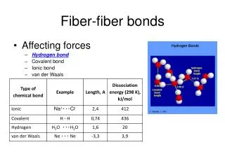
antenna fiber this.... not this