Analysis of Asynchronous Systems
210 likes | 349 Views
Analysis of Asynchronous Systems. Steven P. Miller Michael W. Whalen {spmiller, mwwhalen}@rockwellcollins.com Advanced Computing Systems Rockwell Collins. What Have We Done?. Developed Techniques for Modeling and Analyzing Asynchronous Architectures

Analysis of Asynchronous Systems
E N D
Presentation Transcript
Analysis of Asynchronous Systems Steven P. Miller Michael W. Whalen {spmiller, mwwhalen}@rockwellcollins.com Advanced Computing Systems Rockwell Collins
What Have We Done? • Developed Techniques for Modeling and Analyzing Asynchronous Architectures • Globally Asynchronous/Locally Synchronous (GALS) Architectures • Applied this to the Synchronization Logic of a Dual Flight Guidance System
Why Is This Important? • Most System Architectures are Asynchronous • Distributed Systems • Fault Tolerant Systems • Flight Control, Avionics Displays, … • Asynchronous Behavior is Very Difficult to Get Right • Much More Difficult than Synchronous Behavior • Need to Consider All Possible Interleavings of Components • System Safety Analysis • Involves Both Digital Controller and System to be Controlled • Almost Always Involves Asynchronous Communication
Dual FGS Example • FCS Contains Two Redundant FGS • If A FGS is Active, Then It is Sending Commands to the Pilot or Autopilot • For Most Flight Phases, Only One FGS is Active. • Other Acts as Hot Spare • Passive FGS sets its state to Active FGS • Pilot Flying Side is the Active Side • Transfer Switch Toggles the Pilot Flying Side • If Active Side Fails, Other Side Takes Over • In Critical Phases Both Sides are Active • Final Approach and Go Around • If They Disagree, Both are Disengaged • Independent Mode Determines Whether Both FGS Should Be Active
System Safety Properties • At Least One FGS Shall Always be Active • Exactly One Side Shall be the Pilot Flying Side • If the System is in Independent Mode, Both FGSs Shall be Active Property1 := (Left_FGS_Active | Right_FGS_Active) Property2 := (Left_FGS_Pilot_Flying = !Right_FGS_Pilot_Flying) System_Independent_Mode := Left_Independent_Mode & Right_Independent_Mode Property3 := (System_Independent_Mode -> (Left_FGS_Active & Right_FGS_Active))
Synchronization Properties: Ideal Model • At Least One FGS Shall Always be Active • AG(Property1) ; • Exactly One Side Shall be the Pilot Flying Side • AG(Property2) ; • If the System is in Independent Mode, Both FGSs Shall be Active • AG(Property3); • Reason: Channels Introduce a 1-Step Delay • One Side Does Not “Immediately” Know State of Other Side • Solution: Relax Properties Slightly • Allow Property Not To Hold For One Step • AG( !Property2 -> AX(Property2)) • AG( !Property3 -> AX(Property3))
Asynchrony and Properties • Describe Maximum Interval that Property Can Fail to Hold • Duration (¬P) < T • Pattern: Use Temporal Logic UNTIL Operator to Describe T • Nest P Inside of UNTILs To Match Clock Delays • AG(!P & Sender_Clock -> A[ !Channel_Clock U (P | (AX A[ !Receiver_Clock U P]))])
Asynchrony and Properties LEFT_INTERVAL(Property2) RIGHT_INTERVAL(Property2) • Shorthand for Ease of Presentation • AG(LEFT_INTERVAL(Property2) | RIGHT_INTERVAL(Property2)); • Not Actually Supported in SMV • Need Symmetric Properties for Left and Right Sides • Example: Exactly One Side Shall be the Pilot Flying Side • AG((!Property2 & Left_FGS_Clock -> A[ !LR_Channel_Clock U (Property2 | (AX A[ !Right_FGS_Clock U Property2]))]) | (!Property2 & Right_FGS_Clock -> A[!RL_Channel_Clock U (Property2 | (AX A[!Left_FGS_Clock U Property2]))]))
Synchronization Properties: Asynchronous Model • At Least One FGS Shall Always be Active • AG(Property1) ; • Exactly One Side Shall be the Pilot Flying Side • AG(LEFT_INTERVAL(Property2) | RIGHT_INTERVAL(Property2)); • If the System is in Independent Mode, Both FGSs Shall be Active • AG(LEFT_INTERVAL(Property3) | RIGHT_INTERVAL(Property3)); • Reason for Non-Satisfaction: Synchronization Logic Error • Counterexample: Both Sides Believe That They are Pilot Flying Side • Explanation on Next Page • Solution: Fix Synchronization Logic • All Properties Hold in Corrected Logic • Significantly More Complex than Original Logic
Synchronization Logic: Synchronous Model vs. Asynchronous Model
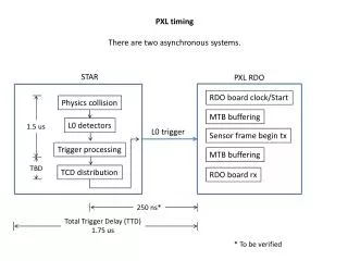
Bounded Asynchrony • Difficult to Prove Anything About Completely Asynchronous Models • All Real Systems are Based on Bounded Asynchrony • Often Exploit Process Rates, Latencies, Drift • FCS System Architecture: • FGSs Run on 100 ms Cycle • FGS Clocks are Not Synchronized • Network Data Transfer Time is <10 ms • FGS Clocks May Drift up to 2 ms Per Cycle • Properties can be Greatly Simplified: • Informally • Duration(!Property) ≤ 300ms • Formally • Count Master Clock Ticks that a Property is False • Prove Count is Less Than Some Maximum
What Is A Calendar? • Describes the “Interesting” Instants In Time • Each Process has a Basic Rate +/- Drift • Each Process has a Counter Until Next Execution (Time_Remaining) • Advance Global Time to Next Instant That A Process Can Execute • If A Process Executes, Reset its Counter to (Rate +/- Drift) • Implementations • Real Time: Rates are Real Numbers (SAL/Prover) • Discrete Time: Define Basic Time Quanta (SMV)
Observations • Asynchrony Makes Modeling Much More Difficult • More Difficult to Get the Models Correct • Subtle Errors are Easy to Make • Asynchrony Makes Analysis Much More Difficult • Properties Are Difficult to State • Require Complicated LTL Formulae • Difficult for Practicing Engineers • Synchronous Architectures are Easier To Analyze • TTA, Spider • Not Always Practical to Make Entire System Synchronous • Example: Mechanical System + Digital Controller • Bounded Asynchrony May Be a Useful Compromise • Calendar Automata Introduces Timing Constraints • Makes Analysis Feasible with Existing Tools • Simplifies Properties • Adds Some Complexity to the Model
Benefits • Approach Is Sufficient For Many Critical Avionics Architectures • Synchronous Architectures: 777 Safebus, TTA, Spider • GALS Architectures: AFDX, Most Existing Federated Architectures • Our Model Is Built on Well-Understood Languages and Tools • Pairing of Synchronous Languages and Temporal Logic • Possible to Express Most Properties of Interest • We Can Analyze System Architectures for Critical Safety Properties • Finds Some of the Most Difficult Errors in System Designs • Possible to Perform Early in Software Lifecycle • Applying it Now to Critical Avionics Systems Under Development