Download
1 / 27
270 likes | 288 Views
This document provides an overview of the preparations for the ATLAS Phase-I Upgrade, specifically focusing on the Insertable B-Layer (IBL) project. It includes information on the project structure, organization, installation scenarios, and requirements for sensors and electronics.

E N D
ATLAS Preparations for LHC Phase-I Upgrade ATLAS Week CERN, July 6th G. Darbo - INFN / Genova Indico AGENDA page: http://indico.cern.ch/conferenceDisplay.py?confId=47255
IBL Status • Project formally started: • Project Leader endorsed by CB (Feb 2009) • IBL Management Board • IBL Kick-off meeting – July 8th– Interested Institutes leaders invited • To converge towards a MoU for the IBL project • IBL General Meeting June 25th & 26th • 42 talks – 2 full day technical discussion • Whole project covered including software • TDR editor • K. Einsweiller is the TDR editor, with Mar Capeans looking at the technical implementation of the document. EB Minutes – 3 April 2009
IBL Project & Organization • The IBL (Insertable B-Layer) is an ATLAS Upgrade project: • It will deliver a fourth pixel layer, including a new beam-pipe, to the Inner Detector • When delivered, it will become a part of the Pixel Detector and of the Inner Detector and the organization will be “absorbed” into the Pixel & ID • The organization structure has: • IBL MB: Management Board to execute the project • IBL IB: Institute Board, which starts today as an extension of the existing Pixel IB and will be chaired by C, Goessling. Pixel Institutes in IBL New Institutes in IBL ATLAS UPO ATLAS UPGRADE IBL MB (Management Board) IBL IB (Institute Board) IBL PL IBL TC IBL Module WG Stave WG I&I WG Off-det WG
Management Board (MB) • Ad-interim membership • IBL Project Leader: G. Darbo • IBL Technical Coordinator: H. Pernegger • “Module” WG (2 Physicists): F. Hügging & M. Garcia-Sciveres • “Stave” WG (1 Phy. + 1 M.E.): O. Rohne + D. Giugni • “IBL Assembly & Installation” WG (2 M.E. initially, a Phy. Later): N. Hartman + R. Vuillermet • “Off-detector” WG (1 Phy. + 1 E.E.): T. Flick + S. Débieux • “Extra” members: • Ex officio: Upgrade Coordinator (N. Hessey), PO Chair (M. Nessi), Pixel PL (B. Di Girolamo), ID PL (P. Wells), Pixel Chair (C. Gößling) • Offline “liaison” Pixel Off-line coordinator: A. Andreazza • TDR editor (temporary): K. Einsweiler • IBL Management Board • Membership: • IBL PL + IBL TC • 2 coordinators from each WG • Plus “extra” members • Module WG • (2 coordinators) • FE-I4 • Sensors • Bump-Bonding • Modules • Test & QC • Irradiation • Stave WG • (1 Phys + 1 Eng.) • Staves • Cooling Design & Stave Thermal Management • HDI • Internal Services • Loaded Stave • Test & QC • IBL Integr.-Install. • (2 Eng.) • Stave Integration • Global Sup. • Beam Pipe (BP) • Ext.services inst. • IBL+BP Installation • Cooling Plant • Test & QC • Off-detector • (1 Phys + 1 E.Eng.) • Power • DCS • ROD • Opto-link • Ext.serv.design/proc. • Test Beam • System Test
Predominant Stave Layouts • Several layouts under study: 14 staves at Rmin=~3.2 cm • Single and double staves – One or two (redundant) cooling channels Sensor Sensor Biturbine Inverted • Ref: N. Hartman: • http://indico.cern.ch/conferenceDisplay.py?confId=43496
Installation Scenarios R. Vuillermet • Two global support / installation scenarios: IBL support tube (1) / no tube (2): • An IBL support tube would have advantage on stiffness and simplicity/safety for IBL installation, but drawback are envelope needs (~1÷1.5 mm) and increase of radiation length • Procedure studied on mock-up at bld.180 - procedure (1) animation: • The beam pipe flange on A-side is to close to the B-layer envelope - Need to be cut on the aluminum section • A structural pipe is inserted inside the Beam Pipe and supported at both sides. • The support collar at PP0 A-side is disassembled and extracted with wires at PP1. • Beam pipe is extracted from the C-side and it pulls the wire at PP1 • New cable supports are inserted inside PST at PP0. • A support carbon tube is pushed inside the PST along the structural pipe. • The support carbon tube is fixed in 2 point of PP0 and on PP1 walls on side C and A. • The structural pipe with a support system is moved out from the support carbon tube. . The new beam pipe (in any configuration with OD up to 82,5 mm) is inserted from A-side. It has 2 supports at PP0 area and 2 floating wall at PP1 on side A and C. C-side A-side Started to setup a 1:1 mock-up of Pixel/beampipe/PP1 in Bat 180
Requirements for Sensors/Electronics • Requirements for IBL • IBL design Peak Luminosity = 3x1034 cm-2s-1 • Integrated Luminosity seen by IBL = 550 fb-1 • Total NIEL dose = 2.4 x 10¹⁵ ± 30% (σpp) ± 50% (damage factor) = 4.7 x 10¹⁵ neq/cm2 • Total radiation dose > 200 Mrad • Fit made for 2 < r < 20 cm for L=1000fb-1 • Gives for IBL @ 3.7 cm (550 fb-1): • Φ1MeV=2.4x10¹⁵ (1.2 MGy) • Safety factors not included in the computation (pp event generator: 30%, damage factor for 1 MeV fluences: 50%) Ref. Ian Dawson - AUW
Module Layout - Convergence • Decision between Planar and 3D sensors will be done after TDR • Need module prototypes with FE-I4 (second half 2010) • Diamonds could be another option • Common sensor baseline for engineering and system purposes • 3D sensors – single chip modules • Planar sensors – 2 chip modules • Gap between sensors: 100µm for mechanical / high voltage requirements • Maximum operating voltage: 1000 V (need more for planar?) Credits: M.Garcia-Sciveres – F. Hügging
3D Sensors • Large collaboration • 15 Laboratories and 3 processing facilities Thickness 230±15 mm Module type single FE-I4 assembly #electrode 2 per 250mm Edge active 5mm Edges guard 200mm Signal (5x10¹⁵) ~12500 e- Bias (5x10¹⁵) ~150V Wcm-2( 5x10¹⁵) 33mW at -10oC Lorentz angle before irr. free Efficiency (3200 e-) 96% (0o) 99% (15o) Wafer dim. 4” Expected yield ~50% Bias bump-b and pad FBK & CNM SINTEF/Stanford Credits: C. Da Via on behalh of ATLAS 3D Sensor R&D
Planar Sensor • Planar sensor R&D approved by sLHC USG • 16 Institutions • High dose (also for IBL) • Low cost – large area @ sLHC • N-on-n & n-on-p • For IBL: • improve radiation hardening • Slim edge (no overlap in Z) • Optimize guard-ring vs. Vbias
3D & Planar – Test Beam (June ‘09) • Comparison of 3D and Planar • Test beam with magnetic field • Planar sensors are sensitive to Lorentz angle: maximize charge at incidence angle = Lorentz angle • 3D (electric field parallel to sensor surface) are not. • Active edge: ~5 to ~10 µm from edge (see picture at the right) 3D FBK ToT at 15o 3200e- planar
Frontend Chip - FE-I4 20.2mm 7.6mm ~200μm Largest Chip in HEP 16.8mm ~19 mm active IBM reticule 8mm active 2.8mm ~2mm Chartered reticule (24 x 32) FE-I3 74% FE-I4 ~89% New FE-I4 Pixel size = 250 x 50 µm2 Pixels = 80 x 336 Technology = 0.13µm Power = 0.5 W/cm2 FE-I3
FE-I4 Status • FE-I4 Status • Prototype blocks in MPW (MOSIS) submitted 3/2008, measurements, irradiation • Design review (3/2009): “Design Technical Issues” on full scale design • FE-I4 Design Collaboration Meeting - Bonn July 1st and 2nd 2009 • Very successful to finalize technical details needed for full design integration • Target date for having complete chip layout done is still September 09 • The technical schedule for each circuit block delivery is being updated • Many interfaces have been finalized and documentation of the details is under way • Internal communication between circuit blocks • data output format headers, configuration read-back, etc. • Partitioning of power "planes" and power-up sequence • Pinout (being updated)
Cooling: CO2 or C3F8 • IBL cooling Ptotal =1.5kW • Prototyping CO2 and C3F8 cooling system in cooperation with ATLAS CERN cooling groups and NIKHEF • Prototype staves and cooling pipes/heater assemblies ready to start measurements on heat transfer coefficient and thermal performance of stave • Pipe material plays important role in thermal gradient: figure of merit is between 16.5 C.cm2/W (CF) and 2.4 C.cm2/W (Ti), Ti therefore allows for higher sensor power before thermal run-away • Choice of coolant influences pipe diameter (CO2: ~1.6mm, C3F8 ~3mm) and minimal evaporation temperature (C3F8 min Tevap=-30C, CO2 min Tevap= -45C) • Want redundancy (2 pipes) to avoid this significant “single point failure” in case of leak/blockage of one pipe Very preliminary & conservative material breakdown for different options: Credits: D. Giugni, P. Schwemling, H. Pernegger
When is IBL Ready to Install? • Difficult answer…: • In February (AUW) we have been told that the installation date was delayed by one year • End of 2012 -> end to 2013 • Today we feel that the 2013 is optimistic • Earliest starting date for Phase I is the 2013/2014 shutdown. • The availability of LINAC4 (around 2014) will define the shutdown for Phase I, upgrade, when the IBL would be installed. • The Upgrade Project Office (May 12th) suggests to use 2014/2015 as a guideline for the IBL installation date. • We are now working with a schedule that foresee an installation date in 2014/2015 • Need to agree with LHC machine on Phase I date -> LHCC • The FE-I4 and Sensor/Module are on the critical path, and installing earlier than 2014/2015 would require some compromises in the performance.
FEI4 drives the schedule for modules • getting the next FEI4 asap is crucial for module qualification Stave 0 plays a crucial to qualify the IBL system (mechanics, staves and off detector electronics) Service installation happens in shutdowns - need definition & procurement of services (USA15->PP2) early on to use shutdown time efficiently Commissioning as part of Pixel system Credits: H. Pernegger
IBL Software - Migration to Athena/G4 • Attilio Andreazza coordinating the activities - mailing list for IBL software development • atlas-ibl-software@cern.ch • Implement IBL in the existing ATLAS software framework • Detector simulation based on Geant 4 • Keep up with material updates in the ID and surroundings • Use existing ATLAS track reconstruction algorithms • Use existing b‐tagging algorithms • Meeting end of July to discuss progress: • G4 geometry implementation (Dmitri Tsybychev) • Implementation of different digitizations (Vadim Kostyukhin) • Simulation of radiation damage (from current pixel community) • Define benchmarks for TDR
TDAQ @ sLHC Phase I • Work has started within Level-1 to • revisit the performance of current L1 algorithms at 1034 and extend to 3x1034 • Understand the benefits of topological information • Hardware changes necessary to propagate/use the topological info L1Calo and L1Muon to understand together how • L1Calo info can be propagated to L1Muon for muon isolation purposes • the max latency available to work within • FTK is a hardware track reconstruction system • It would work on L1A events and produce tracks in the whole InDet (not RoIs) within 10s of µs to be used by L2 (tracking performance similar to L2) • Work has been hampered by difficulty in producing sizable simulation datasets at 1034 • Asked to explore • How FTK deals with 3x1034 (needs simulation) • How FTK can incorporate the IBL • How the FTK compares with expanding the L2 farm • Planning to submit a TDR by end 2009
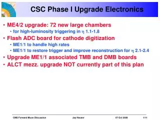
Muon @ sLHC Phase I • Muon detector has large uncertainty (factor 5) on cavern background: • Possible performance degradation in the very forward region 2.0<h <2.7 (CSC region) • Original Muon Spectrometer Design with 2 layers of CSC (8 precision measurements) but currently only one layer installed. • Study the possibility to reinforce the CSC region by inserting a thin (50 mm) detectors to provide more measuring points and possibly pad read-out • Current Options: • TGC • MicroMegas • ThinTubes MDT
New Beam Pipe • From Ray’s presentation to PO 10/6 • http://indico.cern.ch/conferenceDisplay.py?confId=60437 • Need beam pipe ready for integration in SR1 1 year before IBL installation • Beam pipe production ARO long (2 years at manufacturer + 8mo for preparation at Cern ??? - To be verified) • 2009: • Aim to have full technical drawing of beam pipe by end of this year (flanges,..) • Important: Need to make official request to Beam Pipe group now • Start market survey • 25mm radius compatible with aperture and mechanics • Open question to validate this number • larger TAS, smaller VI • Machine induced background • Impedance requirement & Vacuum
IBL kick-off Meeting – Draft Agenda • 9:00 – Introduction – G.Darbo (20 min) • What is IBL project – first project in the upgrade phase I – deliver a 4th layer for the pixel detector – model of resources • Scope of the meeting • 9:30 – Technical Presentation of IBL project - H. Pernegger (30 min) • Where exists a technical baseline • Where are open technical options and what are the planned steps for a convergence • Where technical solutions have not discussed or are very little developed • Manpower figure 10:15 Coffee Break • 10:45 Project Cost – G. Darbo (20 min) • 11:15 Round table – “Wishes and Interest of Institutes” – Chair C. Gößling 12:45 Lunch • 14:15 Sharing of Work – “Interactive Session” G.Darbo, C. Gößling • Fill online a table with work sharing – “the big picture” • Keep note of inputs from round table 16:45 Coffee Break • 17:15 Memorandum of Understanding – M.Nordberg • What should be inside – look at ATLAS construction MoU • How to map “the big picture” into the MoU • 18:00 End of the meeting
MB & WG Operation IBL organization is starting up: • Management Board (IBL MB) • Weekly meeting on Monday – closed meeting – issues tracking • The 4 Working groups (WG) cover the whole project: • WG1 – Module • WG2 – Stave • WG3 – Integration & Installation • WG4 – Off-detector • Mailing lists – open subscription to ATLAS active members • IBL General: atlas-ibl-ge@cern.ch • WG1: atlas-ibl-wg1@cern.ch (alias atlas-ibl-module@cern.ch) • WG2: atlas-ibl-wg2@cern.ch (alias atlas-ibl-wg2@cern.ch) (it was the atlas-pixel-blr-mechanics@cern.ch) • WG3: atlas-ibl-wg3@cern.ch (alias atlas-ibl-IntegrationInstallation@cern.ch) • WG4: atlas-ibl-wg4@cern.ch (alias atlas-ibl-OffDetector@cern.ch) • To subscribe: https://e-groups.cern.ch/
Collaborative Workspace https://espace.cern.ch/atlas-ibl/default.aspx
IBL Cost • Total cost 9.6 MCH: • Use this cost to “shape the project” – revise when better understanding of the design (TDR) • Funding Model: M&O-A, M&O-B, New project money