Download
1 / 17
170 likes | 279 Views
A. Rocchi INFN Roma Tor Vergata. Compensation of thermal effects in future detectors. Outline. Thermal effects Where we stand TCS in current detectors Near future TCS in Advanced detectors ET Thermal effects Compensation options. Thermal effects: a brief introduction.

E N D
A. Rocchi INFN Roma Tor Vergata Compensation of thermal effects in future detectors
Outline • Thermal effects • Where we stand • TCS in current detectors • Near future • TCS in Advanced detectors • ET • Thermal effects • Compensation options A. Rocchi - GWADW 2010 - Kyoto
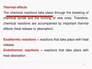
Thermal effects: a brief introduction • In TM, optical power predominantly absorbed by the HR coating and converted into heat temperature gradient inside the substrate • Two different effects are generated: • Non-uniform optical path length distortions (thermal lensing) mainly due to the temperature dependency of the index of refraction wavefront distortions of the fields in the SRC and PRC cavities • Change of the profile of the high reflective face due to thermal expansion (thermo-elastic deformation), in both ITMs and ETMs, affecting the FP cavity. This effect is negligible in current detectors, but becomes relevant in advanced IFOs A. Rocchi - GWADW 2010 - Kyoto
Virgo+ scheme Mirror B Mirror A Half wave plate and fixed polarizer are used for DC power control. This system does not deviate the beam impinging on the AXICON Single AXICON used to convert a Gaussian beam into an annular beam. Size of the annulus hole can be set by moving L3 To monitor the CO2 beam quality, an infrared camera has been installed on each bench. A. Rocchi - GWADW 2010 - Kyoto
TCS noise: already an issue • TCS can inject displacement noise into the detector (see LIGO-P060043-00-Z) • Coupling mechanisms: • Thermo-elastic (TE)- fluctuations in locally deposited heat cause fluctuations in local thermal expansion • Thermo-refractive (TR)- fluctuations in locally deposited heat cause fluctuations in local refractive index • Flexure (F)- fluctuations in locally deposited heat cause fluctuations in global shape of optic • Radiation pressure TE TR F Present detectors already require intensity stabilization of the CO2 laser IR detector noise limited A. Rocchi - GWADW 2010 - Kyoto
Virgo+ TCS performances With 14.5W of IFO input power, Virgo+ TCS has been tested looking at the phase camera images to see the effects of compensation on the shape and position of the sidebands. The optical gain of the ITF increases by about 50%. 14.5W IFO 2.4W total TCS power 17W IFO No TCS, 12W IFO 8.5W total TCS power 4W 6W Coating absorptions play an important role: with new ITMs, you get the same result with only 3W of TCS 6.5W 7W A. Rocchi - GWADW 2010 - Kyoto
TCS in Advanced detectors/1 • One more effect to take care of: displacement of the HR face of all TMs • Change of the ROC, decrease of the spot size on TMs, increase of thermal noise of about 15% (see LIGO-T060083-01-D) • One more actuator: ring heaters to control ROCs of all TMs • Present level of intensity stabilization (10-7/√Hz) not enough to heat with CO2 directly the TM (10-9/√Hz needed) compensation plates required A. Rocchi - GWADW 2010 - Kyoto
TCS in Advanced detectors/2 • The heating profile must be much more precise than in present detectors • Simple system like an axicon is not enough (see VIR-0182A-10) • Too high HOMs content in RF sidebands for MSRC • Necessity to move to active optical elements (MEMs or scanning systems) to generate CP heating pattern Optimized Heating Pattern axicon OHP A. Rocchi - GWADW 2010 - Kyoto
What about 3rd generation detectors? • In a cryogenic IFO with silicon TMs, thermal lensing is likely to be negligible (to be verified with optical simulations) • Thermal expansion coefficient tends to zero • Thermal conductivity increases, higher than 10W/(cm K) between 10 and 100K • dn/dT is small at low temperatures From S. Steinlechner et al, “Absorptions measurements on silicon”, 2nd ET general meeting, Erice A. Rocchi - GWADW 2010 - Kyoto
But if ET is a 2-tone Xylophone? (CQG 27, 2010) • S. Hild et al presented a possible 2-tone configuration for ET at the Erice Meeting • High frequency detector: • High optical power • Room temperature • Low frequency detector: • Low optical power • Cryogenic • Silicon test masses Does ET-HF need TCS? A. Rocchi - GWADW 2010 - Kyoto
Thermal effects in ET-HF • ET-HF uses • Helical LG33 modes • Fused silica test masses • Considering 3MW in the FP cavity and coating absorptions of 0.5ppm, absorbed power is 1.5W (3 times higher than in AdVirgo) A. Rocchi - GWADW 2010 - Kyoto
AdVirgo-like TCS… • Compensation plates (same diameter as TMs) properly heated by CO2 laser • Ring heaters to correct mirrors’ radii of curvature A. Rocchi - GWADW 2010 - Kyoto
… or radiative cooling • If ET-HF and ET-LF are co-located: there would be a lot of cryogenics • Directional radiative cooling working principle (LIGO-G080414-00-R) • The cold source is imaged onto the centre of the test mass • The central area of the test mass is in radiative contact with the cold source • Heat radiated “towards” the cold source is not returned to the test mass • The energy balance is negative, the test mass is cooled S. Hild et al Experiment carried at Caltech with a parabolic mirror (Nucl.Instrum.Meth.A607:530-537,2009.) A. Rocchi - GWADW 2010 - Kyoto
System under test (see VIR-0302A-10) ParabolicReflector Cold Target • From radiative cooling to Parabolic Radiative Cooling • The use of parabolic collectors allows to decrease the dimensions of the cold targets How PRC would look like in an IFO ParabolicCollector A. Rocchi - GWADW 2010 - Kyoto
Experimental set-up • Scaled down system designed, simulated (optically and thermally) and assembled • First tests performed using LiN2 to cool the cold spots 1m A. Rocchi - GWADW 2010 - Kyoto
First data • Some technical issues during first tests • Experimental data show some discrepancies with simulations • Work in progress to identify and mitigate stray effects 300 Work in progress 75 A 10% change in the width of the cooling profile causes a worsening of the thermal lensing compensation quality of a factor of 10 296 286 0 8hrs Optical path length. Strength of the residual lens: 3.4·10-4 dioptres 10% larger 3.5·10-5 dioptres ideal case -4.8·10-4 dioptres 10% smaller A. Rocchi - GWADW 2010 - Kyoto
Conclusions • Current TCS uses carbon dioxide lasers to correct wavefront distortions in PR cavity • Advanced detectors will use a TCS closely related to the present one with minor differences: • CO2 will act on CPs instead of TM • Ring heaters needed to control ROCs of all TMs • A cryogenic IFO may not require TCS • In a 2-tone xylophone, the HF room temperature IFO needs TCS • AdVirgo-like scheme works also for LG33 • PRC under investigation A. Rocchi - GWADW 2010 - Kyoto