Download
1 / 21
210 likes | 455 Views
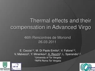
Thermal Compensation System for Virgo+. Alessio Rocchi INFN Roma Tor Vergata. Thermal Lensing. Observed in Virgo through reduction of the sidebands gain. WI. NI. ITMs absorptions evaluated through coupled thermal-modal FEM with Ansys. Red and blue curves experimental frequency shifts.

E N D
Thermal Compensation System for Virgo+ Alessio Rocchi INFN Roma Tor Vergata
Thermal Lensing • Observed in Virgo through reduction of the sidebands gain. A. Rocchi - 24.10.2007 LSC-Virgo Meeting
WI NI ITMs absorptions evaluated through coupled thermal-modal FEM with Ansys Red and blue curves experimental frequency shifts green and pink FEM results 0.025 Df (Hz) New measurement by M. Punturo, NI absorption ~ 4.5 ppm 0 Time span ~25000sec ITMs effective absorptions WI (7.8±1.1) ppm NI (2.3±0.3) ppm Errors come from dependency of the model from uncertainty on elastic parameters dependency on temperature A. Rocchi - 24.10.2007 LSC-Virgo Meeting
Thermal lensing evaluation Beausoleil analitycal solution A. Rocchi - 24.10.2007 LSC-Virgo Meeting
Thermal Compensation System • TCS for Virgo+: annular heating of ITMs with dc CO2 laser • “Annular” profile • from simulations: reasonable parameters to compensate inner radius~2.5 cm, outer radius~11÷14 cm Desirable properties: • It is easily adaptable as new understanding of the ITF is realized • It does not require a significant vacuum incursion to install as this would lead to significant down time to the instrument • Two phases installation: • Feb 2008, system without power stabilization control loop • May-June 2008, installation of the power stabilization control loop A. Rocchi - 24.10.2007 LSC-Virgo Meeting
TCS Power requirements A. Rocchi - 24.10.2007 LSC-Virgo Meeting
Optical layout A. Rocchi - 24.10.2007 LSC-Virgo Meeting
Optical benches positioning NI tower Acoustic enclosure Oven TCS optical bench WI tower A. Rocchi - 24.10.2007 LSC-Virgo Meeting
Single axicon to get the “annular” profile Final design of the Optical Imaging System P. La Penna & E. Genin 100% efficiency 250mm A. Rocchi - 24.10.2007 LSC-Virgo Meeting
UHV ZnSe viewport DN100CF Clear aperture 90mm Two large in-vacuum steering mirrors (f=190mm) Positioning controlled manually in all DOFs Remotely controlled via stepping motors in angular DOFs and one translation A. Rocchi - 24.10.2007 LSC-Virgo Meeting
Schematic view Laser output power control Beam Dump l/2 waveplate Polarizer L1 L2 CO2 Laser AOM Power Meter Beam Dump L3 AXICON Components in the blue box are used for laser power stabilization, will be installed by mid 2008 L4 L5 LX Aiming Laser To in-vacumm steering mirror A. Rocchi - 24.10.2007 LSC-Virgo Meeting
Tests in Tor Vergata Labs before installation on Virgo • Measure the RIN of the laser • So we can have an estimate of the injected noise in the first phase installation • Check the efficiency of the Optical Imaging System A. Rocchi - 24.10.2007 LSC-Virgo Meeting
Preliminary design of the first in-vacuum mirror Material: Aluminum ~800mm T. Zelenova A. Rocchi - 24.10.2007 LSC-Virgo Meeting
252Hz 537Hz Exploring different designs for the in-vacuum optics holders, with T. Zelenova 226Hz A. Rocchi - 24.10.2007 LSC-Virgo Meeting
f0=537Hz Unloaded f0=375Hz Loaded with mirror (2kg) A. Rocchi - 24.10.2007 LSC-Virgo Meeting
Error signal generation • E. Calloni & M. Laval demonstrated that Phase camera 0 + DarkF tools to “measure” TCS • Pine-hole photodiodes error signal generation • Phase camera 1 an upgraded tool to understand sidebands and TCS Pin-hole mirror B5 Photodiodes P1 Signal = P1-P2 P2 This is only one error signal, but two are needed. Investigating the possibility to use the signal from B2 A. Rocchi - 24.10.2007 LSC-Virgo Meeting
CO2 laser power stabilization 20W CO2 Laser New LASY-20S from Access Laser Co, pre-stabilized, temperature tuned (no line hops) PD AOM Critical components PD A. Rocchi - 24.10.2007 LSC-Virgo Meeting
Noise budget Evaluation of TCS noise injected in Virgo+, if RIN is stabilized @ 3×10⁻⁷/√Hz, flat over the frequency range 10 Hz to 1000 Hz, TCS power=1.5W. Virgo+ sensitivity (without monolithic suspensions) Virgo+ sensitivity (with monolithic suspensions) Total Flexural Thermoelastic+Thermorefractive Radiation pressure A. Rocchi - 24.10.2007 LSC-Virgo Meeting
The End A. Rocchi - 24.10.2007 LSC-Virgo Meeting
Max difference ~ 0.3% Building and validating the FE model Comparison with analytical solution Beausoleil (LIGO-P020026-00-D) • DRUM MODE • ANSYS FEM f= 5584.15 Hz • Experimental value f= 5584.7 Hz Difference is 0.55Hz less than 0.01% A. Rocchi - 24.10.2007 LSC-Virgo Meeting
AXICON Possible optical layout A. Rocchi - 24.10.2007 LSC-Virgo Meeting