News from ATF2
260 likes | 397 Views
News from ATF2. Frank Zimmermann KEK visit, 20-24 February 2012 Thanks to P. Bambade, M. Barnes, A. Faus-Golfe , K. Kubo, S . Kuroda, T. Naito, T. Okugi , K. Oide, Y. Papaphilippou, D . Schulte, T. Tauchi , N . Terunuma , N. Toge , R. Tomas.

News from ATF2
E N D
Presentation Transcript
News from ATF2 Frank Zimmermann KEK visit, 20-24 February 2012 Thanks to P. Bambade, M. Barnes, A. Faus-Golfe, K. Kubo, S. Kuroda, T. Naito, T. Okugi, K. Oide, Y. Papaphilippou, D. Schulte, T. Tauchi, N. Terunuma, N. Toge, R. Tomas Status, limits and plan for ATF spot-size tuning Follow up of planned CLIC contributions ground motion sensors, Q1 & Q2 quad’s, extraction kicker Future of ATF beyond 2013/14
ATF related discussions & activities 20.02. conversation w. Katsunobu Oide about ATF2 future 22.02. tour of e-beam welding and STF (A. Yamamoto) 23.02. 6:30 to ~10 am joining Toshiyuki Okugifor beam-size tuning in ATF control room 23.02. 10-12:00 discussing with T. Tauchi& with J. Urakawa 23.02. 15:00 meeting w NobuToge on ATF2 future and proposed CLIC contributions 23.02. 17:00 further discussions with Junji Urakawa 24.02. morning ATF control room, IP-BSM tuning 24.02. 15:00 ATF operation meeting, reports Naito & Okugi & Oroku 24.02. discussion with Toshiaki Tauchi on ATF2 future & CLIC 01.03. 12:00-15:00 back at CERN - lunch w Angeles Faus-Golfe, discussions on fast kicker plan Emails with Mike Barnes, Philip Bambade, NobuhiroTerunuma, A.F.-G.
ATF2 parameters x2.5 x3.0 x3?
ATF IP BSM (Shintake monitor) Shintake monitor shipped from SLAC to Japan under test at U. Tokyo, 2006
ATF IP BSM (Shintake monitor) measured contrast (offset from ideal modulation) at 2 deg “Z scan”
Confusion of signal fluctuation with modulation (if bad S/N) M. Oroku, 2011 • Fluctuation (“fake modulation”) : Δsig / sig ~ 0.18 (for S/N ~ 1/10) • If fake M > expected M, it becomes confusing • Expected M : 0.17 (300 nm) • Expected M : 0.42 (200 nm) Modulation Fluctuation phase scan: change length of one laser path by changing distance of the delay line with piezo in 2012 laser system is improved compared with 2011; more careful setup & optimization of laser paths, focusing & stability
17 February 2012 194.9 +/- 8.29 nm (10 measurements RMS)
T. Okugi, 23.02.2012 IP y spot size tuning • relaxed optics: bx,y*=10 mm x 0.3 mm at present • expected vertical beam size ~70 nm (ex=1.84 nm, ey=15.6 pm) • IP BSM 30 degree mode (no signal at this mode in early 2011) • multiknobs for tuning: always scan ay, Dy, x’ycoupling • scan of xycoupling by upstream skew quadrupole – not orthogonal • scanning the above three knobs for every step of xy; • it would be better to rotate IP BSM, but not possible at the moment • fluctuations in DR vertical orbit leads to change in IP beam size • optimize, re-scan injected orbit with ZV1X corrector (angle at IP), • the dependence is very strong, a change by 0.01 A (3 mrad kick; D orbit < 500 mm) • changes spot size by ~30% • first scan of the skew sextupole(placed at D≠0) showed dependence • this skew sextupole should compensate for net skew sextupole component • in all ATF2 quadrupoles (why is there such component in the first place?) • IP BSM size reduction factor - significant, various contributions • the real beam size is (~0.8 times?) smaller than measured • below about 100 nm one can change to 174 degree mode • attempt to scan DR DfrFaffected timing synchronization with laser
T. Okugi, 23.02.2012 example IP multiknob scans ay scan optimum + 0.02 x’y scan optimum + 0.02 DY scan optimum=-0.05 ay scan optimum + 0.005
other example IP scans T. Okugi, 23.02.2012 xyscan optimum -10A skew sextupole scan (first ever) optimum + 8A ZV1X (incoming orbit) strong dependence – expected?
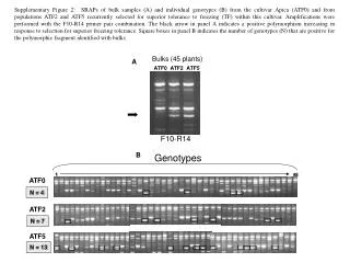
IP y spot size tuning cont’d T. Okugi, & M. Oroku et al, 23.02.2012 • laser wire scan showedabout 165 nm in 10 successive measurements • first time switch to 174 degree mode (which should be used for final tuning!): attempt to find optimal focal range position; • max modulation of 12 % reached; if true signal this would be a beam size around 100 nm • next steps: • towards nominal optics (more favorable background conditions and reduced sensitivity to orbit drifts in the high beta quads) • further strategy – push only by* or bothbx* and by*? • week 13/2: b*y=1.0 mm ; 20/2: b*y=0.3 mm; 5/3: b*y=0.1 mm - however, backed off to higher b*y on 15/03; saw clear modulation with 30 degrees mode for all optics, but background level and signal jitter are increased for decreasing b*y • movable collimator may reduce background • chromaticity and geometric aberration scans not yet applied • understand orbit effect • stabilize extraction line emittance (correlation, orbit feedback?) • longer tuning periods, larger team
174 degree mode sy ~100 nm
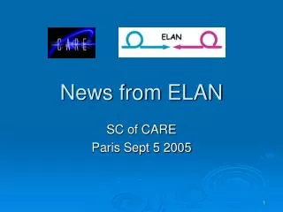
history of beam size sy* [nm] Great Eastern Japan Earthquake & Recovery
P. Bambade present limitations • laser set up & laser stability, intrinsic reduction factor • relaxed optics strategy to move forward? • nonlinear field components in final quadrupolesexpected to be a limit only <60-70 nm; but observation that beam size strongly depends on vertical drift (angle drift at IP); model prediction? • IP BSM Shintakemonitor background on-going effort (halo measurements, simulation study of intercepting apertures, GEANT4 modeling of the post-IP and pre-IP regions, bremstrahlung photon collimation, steering optimisation, choice of beta*); improvements needed to go to 10mm x 0.1 mm (new “nominal”) and even more for ultra-low beta*; also stability will becomemore important • emittance in the extraction line risk factor, lately EXT emittance improved significantly, similar to DR values of ~11-12 pm; however large growth at other times with strong dependances on steering conditions (at the septum, etc.) Likely dominated by non-linear fields (based on intensity dependence studies); wjen DR evolves over time the injected beam trajectory into the EXT changes slightly and can sample different regions of the EXT magnets; emittance blows up and background deteriorates; no good procedure to go back to the narrow good path. • Two suggested ways to tackle this problem: 1) record history plots of DR + EXT trajectory reconstructions and correlate with EXT emittance; 2) study implementation of slow feedback to maintain injection steering within the "good path" (after carefully recording this "good path") Also, an effect it made to ensure that DR steering and tuning procedures include as constraint to keep the same orbit in the region where the beam is extracted. In the long run, maybe the EXT could also be improved with more instrumentation or better magnets • lack of stable tuning time; insufficient training of the team members program for continuous operation would help to achieve more systematic tuning approach, and thus more stability; this requires a larger team of trained operators, to make the effort sustainable over long enough periods; in past weeks, significant progress has been made at KEK in this respect, with essentially only the local ATF staff and Tokyo university students working in the control room; plan to build on this to gradually expand the team of trained operators, such that we can sustain long term tuning efforts at ATF2; this could be critical to reach ATF2 goals; “planned CERN involvement in our new effort for long term stable dedicated operation is also very important, as it will both benefit the project itself and the training of the young people involved on a real system (as opposed to doing only simulation studies)”.
A. Faus-Golfe P. Bambade T. Tauchi training programme from ATF2 Strategy Meeting 15th February 2012
training programme A. Faus-Golfe P. Bambade T. Tauchi The different training periods proposed are: 1) April 9-13 (person-to-person) / April 16-20 (operation practice as sub-shift leaders) 2) April 16-20 (person-to-person) / April 23-27 (operation practice as sub-shift leaders) 3) April 23-27 (person-to-person) / May 14-18 (operation practice as sub-shift leaders) 4) May 14-18 (person-to-person) / May 21-25 (operation practice as sub-shift leaders) 5) May 21-25 (person-to-person) / June 4-8 (operation practice as sub-shift leaders) 6) June 4-8 (person-to-person) / June 11-15 (operation practice as sub-shift leaders)
R. Tomas, ATF TB 12.01.2012 proposed CLIC contributions/prototype tests for ATF2 & their time line on track next talk? require ATF operation in 2014 and beyond plan consolidated
A.Faus-Golfe, M.Barnes, Y. Papaphilippou, N. Terunuma CLIC extraction kicker for ATF stripline kicker unit itself built with Spanish government money by industry, ready end of 2012; this kicker unit will be installed in the ALBA light source for 6 months until end 2013, to check field uniformity and impedance with beam (PhD thesis), then removed from ALBA again matched pulser(inductive adder) produced at CERN, ready by mid 2014 kicker & pulser can be installed at ATF/ATF2 late 2014 or 2015 if kicker replaces existing extraction kicker: 1.5 m free length, 5 mrad if kicker is installed next to the existing kicker: 0.6 m max. length and larger kick angle needed issues: availability of 15-kV pulser, rigidity of striplineelectrodes (deformation from heating caused by SR or wake, difficult masking?) formal proposal for the kicker installation at the ATF: presentation to the next-to-next TB meeting at the end of 2012 or early 2013?!
ATF beyond 2014 • “decision process and time line in KEK not clear” (Katsunobu Oide) • presently following KEK 2008-2013 roadmap • new 5-year roadmap to be developed • change of KEK management April 2012 • 4 new trustees will make the decision
New KEK Management Structure from 1 April 2012 Directors nominated Masanori Yamauchi IPNS DG Atsuto Suzuki Kazuyoshi Yamada IMSS KatsunobuOide Acc L Syuichi Ban Adv RL J-PARC Yet to be nominated JAEA
New KEK Management Structure from 1 April 2012 Trustees nominated Research Promotion Yasuhiro Okada Future Research Plan Int’l Corporation DG Atsuto Suzuki Masaharu Nomura Budget Planning Network NobukazuToge Public Relation J-PARC Yet to be nominated Education
other good news • following my meeting with NobuToge, he, Tauchi-san and Terunuma-san discussed with the KEK DG Suzuki san about the CERN request to know the future plan in view of the proposed hardware contributions • the KEK DG indicated that ATF will certainly (or almost certainly) continue beyond JFY 2013 as a central part of the KEK ILC effort; we could ask to get this in writing if (when) required to proceed with hardware development at CERN
Organizer: Philip Bambade LAL Workshop FJPPL-FKPPL Workshop on ATF2 Accelerator R&D from Monday 19 March 2012 at 08:30 to Tuesday 20 March 2012 at 18:30 (Europe/Zurich) at LAL - Orsay Description: Research on the Accelerator Test Facility 2 at KEK (Japan) is conducted at LAL (Orsay), LLR (Palaiseau) and LAPP (Annecy) in the context of the FJPPL "Toshiko Yuasa" and FKPPL Associated International Laboratories, in close collaboration with several Asian, European and American partners. This workshop will review recent activity, progress and plans towards the two main goals of ATF2: Goal 1 (establish and maintain a 37 nm vertical beam size at the interaction point) and Goal 2 (stabilize the beam spot at the interaction point with a 1-2 nm precision using feedback). In addition, an interim review will be organised for several future projects planned to start in 2012 and beyond, covering both their scientific objectives and technical discussions.
FJPPL, FKPPL, FCPPL? FXPPL = France X Particle Physics Laboratory where X = Japan, Korea, China, Vietnam networks co-funded by CNRS, CEA and the funding agencies in the corresponding country, with the goal to promote / foster joint research and various exchanges of personnel, including students P. Bambade