Download

1 / 40
400 likes | 677 Views
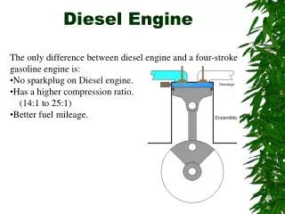
An Ideal Air-Standard Diesel Engine Cycle for Automobiles. 1897 Rudolf Diesel. The MAN B&W 5S50MC 5-cylinder, 2-stroke, low-speed marine diesel engine. This particular engine is found aboard a 29,000 tonne chemical carrier. An ideal Air-Standard Diesel Engine Cycle.

E N D
An Ideal Air-Standard Diesel Engine Cycle for Automobiles 1897 Rudolf Diesel The MAN B&W 5S50MC 5-cylinder, 2-stroke, low-speed marine diesel engine. This particular engine is found aboard a 29,000 tonne chemical carrier
The following problems summarize this section: specific volume
① ② ①→② -Adiabatic compression
② ③ ④ ③ • ②→③ Constant Pressure Expansion • ③→④ - Adiabatic expansion
④ ① • ④→① - Constant Volume Exhaust
Heat Engine for Motorcycles / Cars 2013/3/8- American Indian V-engine Motorcycles: http://youtu.be/qa-uCh2KN_s German, Gottlieb Daimler invented the first gas-engined motorcycle in 1885, which was an engine attached to a wooden bike. That marked the moment in history when the dual development of a viable gas-powered engine and the modern bicycle collided. Gottlieb Daimler used a new engine invented by engineer, Nicolaus Otto. Otto invented the first "Four-Stroke Internal-Combustion Engine" in 1876. He called it the "Otto Cycle Engine" As soon as he completed his engine, Daimler (a former Otto employee) built it into a motorcycle. The Harley Davidson Motorcycle Many of the nineteenth century inventors who worked on early motorcycles often moved on to other inventions. Daimler and Roper, for example, both went on to develop automobiles. However, inventors such as William Harley and the Davidsons brothers continued to develop motorcycles and their business competitors were other new start-up companies such as Excelsior, Indian, Pierce, Merkel, Schickel and Thor. 2014-2-2-TRANSFORMERS-IV coming soon http://youtu.be/Ois4sYdaBKs
An ideal Air-Standard OTTO Engine Cycle Otto cycle engine has a compression volume ratio of 8. At the beginning of the compression process, the working fluid is at 100 kPa, 27°C (300 K), and 800 kJ/kg heat is supplied during the constant volume heat addition process. Using the specific heat values for an air (fuel+air mixture) at 900K for whole cycle. Air (MW=29) was used at average cycle temperature of 900K. Cv(900K)=0.834 kJ/(kg-K), k(900K)= Cp/Cv= 1.344, R= 0.287 kJ/(kg-K). You are asked to do: a) Sketch the pressure-volume [P-v] diagram for this cycle, b) the temperature and pressure of the air at the end of each process c) the net work output per this cycle [kJ/kg] d) the thermal efficiency [η] of this OTTO cycle.
① ② • ①→② -Adiabatic compression
② ③ • ②→③ Constant Volume Expansion
③ ④ • ③→④ - Adiabatic expansion adiabatic
④ ① • ④→① - Constant Volume Exhaust
Note:Using the ratio of specific heat capacities (k= 1.344) and the compression volume ratio (r= 8), thermal efficiency can be determined.
***2011 Turbomeca-Safran made gas turbine tested 1.41 http://youtu.be/N8T1d9qinGw • 2013 French-Safran with Bell company 2.04 http://youtu.be/XqIH0Uvn-vQSakjvpsjv • ***2012 Eurocopter Bevel gear fabrication 5.16 http://youtu.be/oD4jKBOIBwc • 2012 Huey Helicopter Drivetrain show 4.16 http://youtu.be/fELVG8PXvJE • ***2008 Sea-King S-61 rotor head show 7.21 http://youtu.be/83h6QK-oJ4M • ***2009 How it is made, Helicopter by Discovery http://youtu.be/HHODFG3aMHM • How to build a nuclear submarine • ***2013 How to build UK nuclear submarine by BBC 58 http://youtu.be/vkNhBC9lrcU • ***2013 USS Pennsylvania submarine since 1989 49 http://youtu.be/PPe1gMr8eCk • ***2013 Inside-look USS Stealth submarine 45 http://youtu.be/z9x_K-BHM08 • ***2013 History of submarine from 1776-turtle to 1989-Pennsylvania+electrolysis of H2O+ Torpedo+1945-nuclear power to 2020-FORD 45 http://youtu.be/4RSDZMTNpiQ • 2013 Submarine in WW-I GE-U2 sink 145-UK ships 48 http://youtu.be/GYmGRgW60YI • 2013 PCU-Minnesota submarine 38 http://youtu.be/vej09uueWN4 • How to weld a ship by Robots • **2013 NHK+BBC-How Robots change the world 40 http://youtu.be/8zP7yP8hdLE • 2013 American build Robot army 45 http://youtu.be/-rs3OA4ze1E • 2013 Discovery- Rise of Machines 45 http://youtu.be/imc4xQDp_Fs • **2012 Finland Pemamek Welding automation 1023 http://youtu.be/zi_5Pr3HwpY • ***2009 Arc welding ships by Kawasaki Robotics 10 http://youtu.be/NBFSfyZoX-o • 2010 UK-Rolls-Royce Jumbo Jet Engine 1/4 http://youtu.be/UazsDDFsS7Q • 2/4 http://youtu.be/MQlgK5QOu-4; ¾ http://youtu.be/sQPpdmoZhj8 • 4/4 http://youtu.be/zPIYBgZNrsg Viper test http://youtu.be/p-G09RmXPOo • 2011 Cold War Jets http://youtu.be/_RUhIHbxuHE Helicopter Gas Turbine Engine
Coal-Fired Ultra-Super-Critical (USC) Boiler Used for Power Plants The boiler is the most important component of most coal-fired power plants. The boiler heats water until it becomes steam. If the steam condenses (i.e., if water droplets form) inside the turbine, it can cause damage to the turbine blades. To prevent this, when the steam is produced, additional heat is added to superheat it and raise the temperature to 1000ºF at 2400psi (subcritical boilers). This allows the temperature of the steam to drop without forming water droplets. The steam is either recycled and reheated or sent to a cooling tower. As a liquid is heated, its density decreases while the pressure and density of the vapor being formed increases. As temperature and pressure increase, the liquid and vapor densities become closer and closer to each other. At supercritical fluidthe two densities are equal.
Under supercritical (705ºF and 3212psi)conditions, the water does not actually boil; it simply decreases in density until it is a vapor. Supercritical boilers operate at temperatures and pressures above those conditions. As the supercritical steam turns the high-pressure steam turbine, it passes below the critical point and then enters a condenser. The thermodynamic efficiency of a plant using supercritical steam is higher, 40-42%, than that of a similar subcritical plant (subcritical boilers), 36-38%. Ultra-supercritical (USC) applies to boilers that operate using pressures over 4400psi. These advanced boilers take advantage of further increases in efficiency and two-stage reheating to reach a thermodynamic efficiency of 48%. Supercritical boilers were first developed in the U.S. in the 1950s. Today, time, experience, and the continuing development of high pressure / temperature materials have made them more robust and flexible. Supercritical boilers are used for all large capacity boiler operations in Japan as well as most European and Asian countries. There are more than 400 supercritical boiler plants in operation worldwide. In the U.S., power companies have been slower to adopt supercritical boilers because most of the plants operating today are very old. Continuing technology advances and strict federal emission standards for new plants will compel companies to adopt the most efficient technologies possible. The Department of Energy funds several programs with industry that have resulted in cost-effective, efficient, low emission designs for new plants that use supercritical technology. Supercritical technology may become the standard for new plants and possibly for plants that are ready for repowering.
It is important to note that the boiler technology for a given plant is virtually independent of the combustion unit for that plant. Supercritical technology has proven to be effective with virtually every type, configuration, and size of combustor. This means that almost any plant, whether old or new, can be upgraded to a supercritical boiler to increase the overall plant efficiency. There is a high level of confidence in the technology, and material costs are only 2% higher than for a similar subcritical design. And new developments in high temperature materials are paving the way for the adoption of USC boilers. In the boilers, as the temperature and pressure used for steam increases, the efficiency of the boiler increases as well. The main factor limiting the temperature that can be used is the material used in the piping and fittings. So, to compliment the supercritical technology.
Schematic Flow Diagram of Supercritical (Once Through) Boiler Technology
BENSON Boiler Advantages - Higher thermal efficiency - Full steam temperature controllability over a wide load range, thus taking wide range of coal quality - Faster start-up and cooling down of the boiler - High reliability for emergency load runback - Operation is as easy as Drum boiler - Advantages of Spiral Water Wall - High Reliability of Water Wall Tube- Spiral water wall with ribbed tubes achieves an equalization of furnace exit fluid temperature - Proven Operating Record- Spiral Water Wall has a proven operating record when applied with Opposed Firing. The probability of tube failures is minimized - Low Water System Pressure Drop- With no orifices, proper pressure loss and flow balance is easy to maintain - Spiral W/W uses a high mass velocity design, therefore, heat transfer and flow, outlet fluid temperature is not affected by sudden changes in pulverizer or burner operation - Easy Boiler Commissioning- With no orifices, there is no need to adjust the tube flow during startup and testing - Maintenance Free- With no orifices, scaling is eliminated as a maintenance issue to maintain proper flow - High Mass velocity achieves higher heat transfer
Real Equipments Diagram of Supercritical (Once Through) Boiler Technology MidAmerican Energy Company Walter Scott, Jr. Energy Center, Unit 4
The Lastest USC Boilers in Japan EPDC Tachibanawan Unit 2 Tokyo Electric Power Co., Ltd Hitachi Naka Unit 1
Alston-3D model for SF Boiler Unit with platforms and auxiliary equipment 2013 Alston http://youtu.be/W2AD34CPI7E With the 1000 MW Manjung 4, Malaysia looks set to be the first country in Southeast Asia to not only boast an ultra-supercritical power station, but one where both the boiler and the steam turbine are being manufactured in Asia.
In a supercritical plant, steam pressure is maintained above the critical point of water, which occurs at 221.2 bar, 374 ºC. Beyond this critical point, the two-phase mixture of water and steam found in more conventional power plant boilers ceases to exist. Instead the fluid enters a new 'supercritical' state. As a consequence, the conversion from water to steam occurs entirely within the evaporator circuits and there is no need for a boiler drum, necessary in a conventional subcritical plant. Higher temperatures and pressures however place greater demands on pressure part materials, and as a consequence many new materials have been developed for boilers. The most advanced supercritical plants today are capable of achieving an efficiency of between 40 per cent and 45 per cent (HHV basis), but actual performance depends on specific site conditions, such as cooling water temperature, hence condenser performance. Another important parameter is coal quality. Globally, the quality of available coal is tending to fall as the best coals are exhausted. Modern high-capacity steam plants must now be able to cope with a wider range of coals than has traditionally been the case. With these limitations in mind, the new plant at Manjung 4 is being specified with an efficiency of close to 40 per cent, according to TNB. This is nearly five percentage points higher than the existing three subcritical units at Manjung, which operate at 35 per cent efficiency.
The boiler chosen for the Manjung 4 plant is a vertical tube furnace wall, two-fireball, two pass design equipped with Alstom's LNTFS firing system. The main technical data for the unit are shown in Table 3. With a main steam flow of 3226 tonnes/hour (t/h) at 282 bar and 600 ºC, the unit is classified as an ultra-supercritical design, considered the state-of-the-art today. The boiler for Manjung 4 is Alstom's latest once-through, sliding pressure design and builds on more than 50 years of supercritical development. The new vertical tube design incorporates two important features to allow sliding pressure operation. The first is rifled tubing, which spins the water/steam mixture travelling within the tubes, throwing the water onto the tube surface to aid cooling. The second is the use of orifices to distribute fluid flow to the furnace wall tubes in proportion to tube heat absorption. Tubes in the centre of the wall receive more heat and require more cooling, so proper fluid distribution reduces temperature differentials and consequently the stress within the furnace wall.
The vertical tube design is suited to larger units such as that at Manjung 4 and the self-supporting tubes and the relative simplicity of the design make for a lower construction cost. In addition, the design makes leaks easier to identify and repair and so reduces maintenance costs. The additional choice of a two-pass rather than a tower boiler allows for a shorter overall design. Sliding-pressure operation provides flexibility during daily load swings by allowing the plant to operate more efficiently at part load. The sliding-pressure mode reduces the boiler pressure as load falls, minimizing throttle valve energy losses and therefore helps maintain high steam temperature to the turbine. This also reduces thermal stress during cycling, lowering maintenance and improving availability.
Advanced steam turbine The steam turbine for the new plant will be a 1080 MW-rated STF100 unit equipped with one high-pressure turbine, one intermediate-pressure turbine and two double-flow, low-pressure turbines. Steam conditions, as noted in Table 3, include a high-pressure steam turbine inlet temperature of 270 bar, a steam inlet temperature of 595 ºC and a steam flow from the boiler of 3226 t/h. Reheat steam flow will be 2687 t/h at a temperature of 603.5 ºC. The inlet temperature of steam exiting the steam turbine for the reheater is 364 ºC and the condenser vacuum is 75 mbar. As with the boiler, fabrication of the steam turbine will take place in China at the Alstom Beizhong Power (Beijing) Company Limited. Like its Wuhan facility, Alstom purchased the facility and has equipped it to be able to manufacture advanced turbines of different types. While the Beijing manufacturing plant is designed to serve the large Chinese market it will also fabricate units to be delivered to other parts of the world, including Malaysia. However, many of the components are manufactured in other parts of the world and then shipped to the Beijing plant for assembly. For example, the rotor for the Manjung 4 turbine will be made in Switzerland and the casings in Poland, while other parts will be manufactured in Mexico. The condenser is based on a double condenser arrangement and will be manufactured in Taiwan under sub-contract. As with the existing units at the site, Manjung 4's condenser will utilise seawater cooling, ideal given the island location of the power plant. Water for the plant will be brought onshore to a pumping station via a seabed channel linked to an intake 1.7 km offshore. This water is used for cooling of the plant; about 20 per cent of the cooling water is used for the seawater FGD system, before it is then discharged to the sea. In addition to the main steam turbine, Manjung 4 will also be equipped with a small steam turbine to drive its two feedwater pumps. This steam turbine will be manufactured by Alstom Germany, which is based in Mannheim. Flexible design of generator The generator for the plant will be an Alstom GIGATOP two-pole unit with a generating capacity of 1000 MW. Based on the evolution of a well proven design first developed during the 1970s, the unit will have a water-cooled stator winding, while both the stator core and the rotor will be hydrogen-cooled. The cooling system is designed to enable the machine to maintain high-efficiency at part load as well as full load. Water cooling is carried out by passing deionized water through stainless steel tubes in order to avoid any corrosion problems. Meanwhile hydrogen cooling is conducted using a triple-circuit hydrogen sealing system to minimise losses, and hence operating costs. The stator core is designed to be maintenance-free for the lifetime of the unit.
One of the novel features of Manjung 4, and one that it shares with the previous Manjung units, is the use of seawater flue gas desulphurisation. However the design of the unit has been refined since the earlier installation. The new FGD system is also larger. As you would expect, seawater FGD use seawater itself as the absorbent. Seawater is naturally slightly alkaline and will absorb and react with SO2, converting it in the presence of oxygen from the air, into soluble sulphate, which remains dissolved in the seawater. Absorption takes place in a packed-tower counterflow absorber into which is fed around 20 per cent of the seawater drawn into the plant from the seawater intake system. The process is capable of absorbing above 90 per cent of the SO2, depending on input levels. Once the seawater exits the absorber tower it is sent to a seawater treatment plant where it is mixed with the cooling water exiting the condenser, and treated with ambient air to increase the dissolved oxygen level. The treated water is then returned to the sea. Passage through the FGD system leads to a slight increase in the sulphate load of the seawater, of about 55 mg/l. The pH of the seawater is also lowered, from around 7-8 at the intake to 6-7 when it is returned to the sea. These changes, however, satisfy even very stringent environmental standards, with the process generating no by-products. Seawater FGD has both low lifetime and maintenance costs, Alstom says. Meanwhile, the flue gas exiting the FGD plant is reheated in order to rise high into the air and disperse after leaving the stack. Reheating of the flue gas is done via the gas-gas heater (GGH) with the heat that was extracted from the flue gas before the absorber. The performance specification for the system at Manjung 4 is detailed in Table 5. Sulphur dioxide emission levels are guaranteed at below 200 mg/Nm3, which is significantly lower than the current World Bank standard of 500 mg/Nm3.
Large-scale, versatile PM filtration In addition to low-NOx burners and seawater FGD for emission control, Manjung 4 will also be equipped with a fabric filtration system to control emissions of particulate matter (PM), and will be located upstream of the seawater FGD unit. The three 700 MW units already operating at Manjung all have electrostatic precipitators (ESPs) and so the choice of a fabric filter instead of an ESP may seem unusual but as with many other features of Manjung 4, it is dictated by the available fuel. An ESP will often offer the optimum particulate removal system provided the fuel specification is tight, but when a plant must, like Manjung 4, be able to operate with a range of different coals then a fabric filter is considered more reliable and can maintain performance, irrespective of the coal type and source. For Manjung 4, Alstom will be installing its first 1000 MW fabric filter. The unit will use the company's Optipulse pulse-jet fabric filter system. This system comprises a large number of individual filter bags supported on wire cages, and the complete filter is divided into a series of compartments that can each be isolated using dampers at the inlets and outlets. The flue gas enters the individual bags from the outside and then exits from the top of the interior of the bag. Meanwhile, the filtered particulates are deposited gravimetrically into hoppers below the bags. Cleaning of the bags is by a pulse of compressed air, which inflates the bag sharply to it extreme limit, dislodging dust from the exterior which is then collected in the hoppers. Ash from the fabric filter at Manjung 4 will be exported from the site for reuse at a local cement plant.
Emerson USC Power Plants PITTSBURGH (September 30, 2010) — Emerson Process Management has been selected to install its Ovation™ expert control system at two new 1,000-MW, ultra-supercritical, coal-fired power generating units now under construction at the Anhui Tongling power plant in China’s Anhui province. The contract for automating the new units – which are the first 1,000-MW units in this province – was awarded by China Northwest Electric Design Institute, general contractor for the project. The control system installation is part of Anhui Tongling's Phase VI expansion project, in which older and less-efficient power generating units are being replaced by ultra-supercritical units 5 and 6. Bringing the new units online, expected to occur in February 2011 and May 2011, respectively, will help meet the growing needs of industry in the area and support local economic development.
The world largest USC Power Plants in Jeddah Saudi 沙烏地國首府吉達市