Download
1 / 15
1.55k likes | 4.2k Views
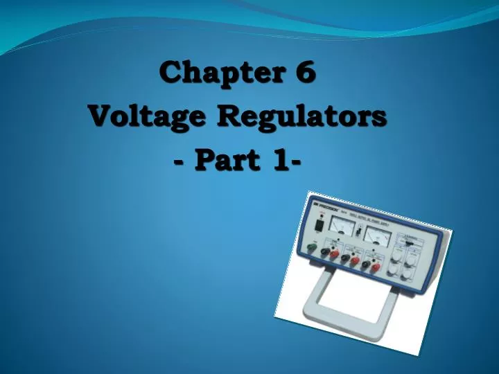
Chapter 6 Voltage Regulators - Part 1-. VOLTAGE REGULATION. Two basic categories of voltage regulation are: line regulation; load regulation. The purpose of line regulation is to maintain a nearly constant output voltage when the input voltage varies.

E N D
Chapter 6 Voltage Regulators - Part 1-
VOLTAGE REGULATION • Two basic categories of voltage regulation are: • line regulation; • load regulation. • The purpose of line regulation is to maintain a nearly constant output voltage when the input voltage varies. • The purpose of load regulation is to maintain a nearly constant output voltage when the load varies.
Line Regulation Figure 6–2 Line regulation. A change in input (line) voltage does not significantly affect the output voltage of a regulator (within certain limits).
Line Regulation Line regulation can be defined as the percentage change in the output voltage for a given change in the input voltage. (6-1) Δ means “a change in”. Line regulation in %/V can be calculated using the following formula: (6-2)
Load Regulation Figure 6–3 Load regulation. A change in load current has practically no effect on the output voltage of a regulator (within certain limits).
Load Regulation Load regulation can be defined as the percentage change in the output voltage from no-load (NL) to full-load (FL). (6-3) where VNL = the no-load output voltage VFL = the full-load output voltage
Load Regulation Sometimes the equivalent Thevenin resistance of a supply is specified in place of a load regulation specification. In this case, VOUT can be found by applying the voltage divider rule: Power Supply In terms of resistances, load regulation can be expressed as:
TYPES OF REGULATOR The fundamental classes of voltage regulators are linear regulators and switching regulators. Two basic types of linear regulator are the series regulator and the shunt regulator. The series regulator is connected in series with the load and the shunt regulator is connected in parallel with the load. Figure 6.4 Series and shunt regulators.
Series Regulator Circuit Figure 6.5Block diagram of the basic connection of a series regulator circuit. • The control element is a pass transistor in series with the load between the input and output. • The error detector compares the sample voltage with a reference voltage and causes the control element to compensate in order to maintain a constant output voltage.
Basic Op-amp Series Regulator Figure 6.6Basic op-amp series regulator. • The resistor R2and R3sense a change in the output voltage and provide a feedback voltage. The error detector compares the feedback voltage with a Zener diode reference voltage. • The resulting difference voltage causes the transistor Q1 controls the conduction to compensate the variation of the output voltage. The output voltage will be maintained at a constant value.
(6-5) The closed-loop voltage gain is:
EXAMPLE Determine the output voltage for the regulator in Figure below. Answer: VOUT = 10.2 V
Series Regulator with constant-current limiting Current limiting prevents excessive load current. Q2 will conduct when the current through R4 develops 0.7 V across Q2’s VBE. This reduces base current to Q1, limiting the load current. The current limit is: For example, a 1.4 W resistor, limits current to about 0.5 A.
Regulator with Fold-back current limiting Fold-back current limiting drops the load current well below the peak during overload conditions. Q2 conducts when VR5 +VBE = VR4 and begins current limiting. VR5 is found by applying the voltage-divider rule: An overload causes VR5 to drop because VOUT drops. This means that less current is needed to maintain conduction in Q2 and the load current drops.