Download

1 / 37
370 likes | 529 Views
Learn about decoders and selectors in digital circuits, their functions, design procedures, and practical applications in hardware design principles. Explore the concept of decoder expansion and building various decoders for efficient circuit design.

E N D
IKI10201 05c-Decoders, Selectors, etc. Bobby Nazief Semester-I 2005 - 2006 • The materials on these slides are adopted from: • CS231’s Lecture Notes at UIUC, which is derived from Howard Huang’s work and developed by Jeff Carlyle; • Prof. Daniel Gajski’s transparency for Principles of Digital Design.
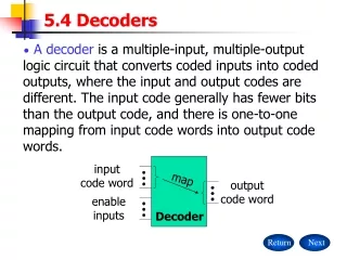
Decoders • Next, we’ll look at some commonly used circuits: decoders and selectors (multiplexers or MUXes). • They can be used to implement arbitrary functions. • We are introduced to abstraction and modularity as hardware design principles.
What is a decoder? • In older days, the (good) printers used be like typewriters: • To print “A”, a wheel turned, brought the “A” key up, which then was struck on the paper. • Letters are encoded as 8 bit (ASCII) codes inside the computer. • When the particular combination of bits that encodes “A” is detected, we want to activate the output line corresponding to A • (Not actually how the wheels worked) • How to do this “detection” : decoder • General idea: given a k bit input, • Detect which of the 2^k combinations is represented • Produce 2^k outputs, only one of which is “1”.
What a decoder does • A n-to-2ndecoder takes an n-bit input and produces 2n outputs. The n inputs represent a binary number that determines which of the 2n outputs is uniquely true. • A 2-to-4 decoder operates according to the following truth table. • The 2-bit input is called S1S0, and the four outputs are Q0-Q3. • If the input is the binary number i, then output Qi is uniquely true. • For instance, if the input S1 S0 = 10 (decimal 2), then output Q2 is true, and Q0, Q1, Q3 are all false. • This circuit “decodes” a binary number into a “one-of-four” code.
How can you build a 2-to-4 decoder? • Follow the design procedures from last time! We have a truth table, so we can write equations for each of the four outputs (Q0-Q3), based on the two inputs (S0-S1). • In this case there’s not much to be simplified. Here are the equations: Q0 = S1’ S0’ Q1 = S1’ S0 Q2 = S1 S0’ Q3 = S1 S0
Enable inputs • Many devices have an additional enable input, which is used to “activate” or “deactivate” the device. • For a decoder, • EN=1 activates the decoder, so it behaves as specified earlier. Exactly one of the outputs will be 1. • EN=0 “deactivates” the decoder. By convention, that means all of the decoder’s outputs are 0. • We can include this additional input in the decoder’s truth table:
Q0 = S1’ S0’ Q1 = S1’ S0 Q2 = S1 S0’ Q3 = S1 S0 Blocks and abstraction • Decoders are common enough that we want to encapsulate them and treat them as an individual entity. • Block diagrams for 2-to-4 decoders are shown here. The names of the inputs and outputs, not their order, is what matters. • A decoder block provides abstraction: • You can use the decoder as long as you know its truth table or equations, without knowing exactly what’s inside. • It makes diagrams simpler by hiding the internal circuitry. • It simplifies hardware reuse. You don’t have to keep rebuilding the decoder from scratch every time you need it. • These blocks are like functions in programming!
A 3-to-8 decoder • Larger decoders are similar. Here is a 3-to-8 decoder. • The block symbol is on the right. • A truth table (without EN) is below. • Output equations are at the bottom right. • Again, only one output is true for any input combination. Q0 = S2’ S1’ S0’ Q1 = S2’ S1’ S0 Q2 = S2’ S1 S0’ Q3 = S2’ S1 S0 Q4 = S2 S1’ S0’ Q5 = S2 S1’ S0 Q6 = S2 S1 S0’ Q7 = S2 S1 S0
Building a 3-to-8 decoder • You could build a 3-to-8 decoder directly from the truth table and equations below, just like how we built the 2-to-4 decoder. • Another way to design a decoder is to break it into smaller pieces. • Notice some patterns in the table below: • When S2 = 0, outputs Q0-Q3 are generated as in a 2-to-4 decoder. • When S2 = 1, outputs Q4-Q7 are generated as in a 2-to-4 decoder. Q0 = S2’ S1’ S0’ = m0 Q1 = S2’ S1’ S0 = m1 Q2 = S2’ S1 S0’ = m2 Q3 = S2’ S1 S0 = m3 Q4 = S2 S1’ S0’ = m4 Q5 = S2 S1’ S0 = m5 Q6 = S2 S1 S0’ = m6 Q7 = S2 S1 S0 = m7
Decoder expansion • You can use enable inputs to string decoders together. Here’s a 3-to-8 decoder constructed from two 2-to-4 decoders:
So what good is a decoder? • Do the truth table and equations look familiar? • Decoders are sometimes called minterm generators. • For each of the input combinations, exactly one output is true. • Each output equation contains all of the input variables. • These properties hold for all sizes of decoders. • This means that you can implement arbitrary functions with decoders. If you have a sum of minterms equation for a function, you can easily use a decoder (a minterm generator) to implement that function. Q0 = S1’ S0’ Q1 = S1’ S0 Q2 = S1 S0’ Q3 = S1 S0
Design example: addition • Let’s make a circuit that adds three 1-bit inputs X, Y and Z. • We will need two bits to represent the total; let’s call them C and S, for “carry” and “sum.” Note that C and S are two separate functionsof the same inputs X, Y and Z. • Here are a truth table and sum-of-minterms equations for C and S. C(X,Y,Z) = m(3,5,6,7) S(X,Y,Z) = m(1,2,4,7) 0 + 1 + 1 = 10 1 + 1 + 1 = 11
Decoder-based adder • Here is how a 3-to-8 decoder implements C and S as sums of minterms C(X,Y,Z) = m(3,5,6,7) S(X,Y,Z) = m(1,2,4,7)
Selectors/Multiplexers • Now we’ll study multiplexers, which are just as commonly used as the decoders we presented last time. Again, • Multiplexers can implement arbitrary functions. • We will put these circuits to use in later weeks, as building blocks for more complex designs.
Multiplexers • A 2n-to-1 multiplexer sends one of 2n input lines to a single output line. • A multiplexer has two sets of inputs: • 2ndata input lines • n select lines, to pick one of the 2n data inputs • The mux output is a single bit, which is one of the 2n data inputs. • The simplest example is a 2-to-1 mux: • The select bit S controls which of the data bits D0-D1 is chosen: • If S=0, then D0 is the output (Q=D0). • If S=1, then D1 is the output (Q=D1). Q = S’ D0 + S D1
More truth table abbreviations • Here is a full truth table for this 2-to-1 mux, based on the equation: • Here is another kind of abbreviated truth table. • Input variables appear in the output column. • This table implies that when S=0, the output Q=D0, and when S=1 the output Q=D1. • This is a pretty close match to the equation. Q = S’ D0 + S D1
A 4-to-1 multiplexer • Here is a block diagram and abbreviated truth table for a 4-to-1 mux. Q = S1’ S0’ D0 + S1’ S0 D1 + S1 S0’ D2 + S1 S0 D3
Implementing functions with multiplexers • Muxes can be used to implement arbitrary functions. • One way to implement a function of n variables is to use an n-to-1 mux: • For each minterm mi of the function, connect 1 to mux data input Di. Each data input corresponds to one row of the truth table. • Connect the function’s input variables to the mux select inputs. These are used to indicate a particular input combination. • For example, let’s look at f(x,y,z) = m(1,2,6,7).
A more efficient way • We can actually implement f(x,y,z) = m(1,2,6,7) with just a 4-to-1 mux, instead of an 8-to-1. • Step 1: Find the truth table for the function, and group the rows into pairs. Within each pair of rows, x and y are the same, so f is a function of z only. • When xy=00, f=z • When xy=01, f=z’ • When xy=10, f=0 • When xy=11, f=1 • Step 2: Connect the first two input variables of the truth table (here, x and y) to the select bits S1 S0 of the 4-to-1 mux. • Step 3: Connect the equations above for f(z) to the data inputs D0-D3.
Buses • Bus drivers have three possible output values: 0, 1, and Z (high impedance ~ disconnection)
Priority Encoders • Encoder is opposite of Decoder, but with priority for MSB
Magnitude Comparators • Comparator compares two integers A and B and sets: • G = 1 when A > B • L = 1 when A < B • G = L = 0 when A = B
Shifter & Rotators • Shifter shifts input bits to the left/right • Shift left: X3X2X1X0 X2X1X00 • Shift right: X3X2X1X0 0X3X2X1 • Rotator is a Shifter with additional shift from one end to the other: • Rotate left: X3X2X1X0 X2X1X0X3 • Rotate right: X3X2X1X0 X0X3X2X1
2k x n ROM ADRS OUT CS k n Read Only Memory (ROM) • A read-only memory, or ROM, is a special kind of memory whose contents cannot be easily modified. • Data is stored onto a ROM chip using special hardware tools. • ROMs are useful for holding data that never changes. • Arithmetic circuits might use tables to speed up computations of logarithms or divisions. • Many computers use a ROM to store important programs that should not be modified, such as the system BIOS. • PDAs, game machines, cell phones, vending machines and other electronic devices may also contain non-modifiable programs.
Memories and functions • ROMs are actually combinational devices, not sequential ones! • You can’t store arbitrary data into a ROM, so the same address will always contain the same data. • You can think of a ROM as a combinational circuit that takes an address as input, and produces some data as the output. • A ROM table is basically just a truth table. • The table shows what data is stored at each ROM address. • You can generate that data combinationally, using the address as the input. • Data = F(A0,A1,A2)
Implementing functions with decoders • We can already convert truth tables to circuits easily, with decoders. • For example, you can think of this old circuit as a memory that “stores” the sum and carry outputs from the truth table on the right.
Implementing functions with ROM • ROMs are based on this decoder implementation of functions. • A blank ROM just provides a decoder and several OR gates. • The connections between the decoder and the OR gates are “programmable,” so different functions can be implemented. • To program a ROM, you just make the desired connections between the decoder outputs and the OR gate inputs.
Implementing functions with ROM (cont.) • Here are three functions, V2V1V0, implemented with an 8 x 3ROM. • Blue crosses (X) indicate connections between decoder outputs and OR gates. Otherwise there is no connection. A2 A1 A0 V2 = m(1,2,3,4) V1 = m(2,6,7) V0 = m(4,6,7)
A2 A1 A0 V2 V1 V0 The same example again • Here is an alternative presentation of the same 8 x 3 ROM, using “abbreviated” OR gates to make the diagram neater. V2 = m(1,2,3,4) V1 = m(2,6,7) V0 = m(4,6,7)
A2 A1 A0 V2 V1 V0 Why is this a “memory”? • This combinational circuit can be considered a read-only memory. • It stores eight words of data, each consisting of three bits. • The decoder inputs form an address, which refers to one of the eight available words. • So every input combination corresponds to an address, which is “read” to produce a 3-bit data output.
ROMs vs. RAMs • There are some important differences between ROM and RAM. • ROMs are “non-volatile”—data is preserved even without power. On the other hand, RAM contents disappear once power is lost. • ROMs require special (and slower) techniques for writing, so they’re considered to be “read-only” devices. • Some newer types of ROMs do allow for easier writing, although the speeds still don’t compare with regular RAMs. • MP3 players, digital cameras and other toys use CompactFlash, Secure Digital, or MemoryStick cards for non-volatile storage. • Many devices allow you to upgrade programs stored in “flash ROM.”
Programmable logic arrays (PLAs) • A ROM is potentially inefficient because it uses a decoder, which generates all possible minterms. No circuit minimization is done. • Using a ROM to implement an n-input function requires: • An n-to-2n decoder, with n inverters and 2n n-input AND gates. • An OR gate with up to 2n inputs. • The number of gates roughly doubles for each additional ROM input. • A programmable logic array, or PLA, makes the decoder part of the ROM “programmable” too. Instead of generating all minterms, you can choose which products (not necessarily minterms) to generate.
Inputs OR array AND array Outputs A blank 3 x 4 x 3 PLA • This is a 3 x 4 x 3 PLA (3 inputs, up to 4 product terms, and 3 outputs), ready to be programmed. • The left part of the diagram replaces the decoder used in a ROM. • Connections can be made in the “AND array” to produce four arbitrary products, instead of 8 minterms as with a ROM. • Those products can then be summed together in the “OR array.”
Example: PLA minimization • For a PLA, we should minimize the number of product terms for all functions together (K-Map minimization individual function). • We should express V2, V1 and V0 with no more than four total products. V2 = m(1,2,3,4) V1 = m(2,6,7) V0 = m(4,6,7) V2 = xy’z’ + x’z + x’yz’ V1 = x’yz’ + xy V0 = xy’z’ + xy
V2 = m(1,2,3,4) = xy’z’ + x’z + x’yz’ V1 = m(2,6,7) = x’yz’ + xy V0= m(4,6,7) = xy’z’ + xy Example: PLA implementation • So we can implement these three functions using a 3 x 4 x 3 PLA: A2 A1 A0 xy’z’ xy x’z x’yz’ V2 V1 V0
PLA evaluation • A k x m x n PLA can implement up to n functions of k inputs, each of which must be expressible with no more than m product terms. • Unlike ROMs, PLAs allow you to choose which products are generated. • This can significantly reduce the fan-in (number of inputs) of gates, as well as the total number of gates. • However, a PLA is less general than a ROM. Not all functions may be expressible with the limited number of AND gates in a given PLA. • In terms of memory, a k x m x n PLA has k address lines, and each of the 2k addresses references an n-bit data value. • But again, not all possible data values can be stored.