Download

1 / 33
380 likes | 656 Views
Decoders. Decoders. • A decoder is a circuit which takes an n-bitnumber as input and uses it to select (set to1) exactly one of its 2n outputs. 3 input to 8 output decoder. Q0 Q1 Q2 Q3 Q4 Q5 Q6 Q7. B0 B1 B2 E. E B2 B1 B0 Q0 Q1 Q2 Q3 Q4 Q5 Q6 Q7

E N D
Decoders • A decoder is a circuit which takes an n-bitnumber as input and uses it to select (set to1) exactly one of its 2n outputs
3 input to 8 output decoder Q0 Q1 Q2 Q3 Q4 Q5 Q6 Q7 B0 B1 B2 E • E B2 B1 B0 Q0 Q1 Q2 Q3 Q4 Q5 Q6 Q7 • 0 0 0 0 0 1 1 1 1 1 1 1 • 0 0 0 1 1 0 1 1 1 1 1 1 • 0 0 1 0 1 1 0 1 1 1 1 1 • 0 0 1 1 1 1 1 0 1 1 1 1 • 0 1 0 0 1 1 1 1 0 1 1 1 • 0 1 0 1 1 1 1 1 1 0 1 1 • 0 1 1 0 1 1 1 1 1 1 0 1 • 0 1 1 1 1 1 1 1 1 1 1 0 • 1 X X X 1 1 1 1 1 1 1 1
Encoders D0 D1 D2 D3 Q0 Q1 V Encoded Outputs Data Inputs Output Valid An encoder performs the opposite function to a decoder, it produces a binary output that indicates which input is active. There are often PRIORITY encoders because they encode the most significant input. Eg. A 4 input priority encoder. D0 D1 D2 D3 Q0 Q1 V 0 0 0 0 0 0 0 1 0 0 0 0 0 1 X 1 0 0 1 0 1 X X 1 0 0 1 1 X XX 1 1 1 1
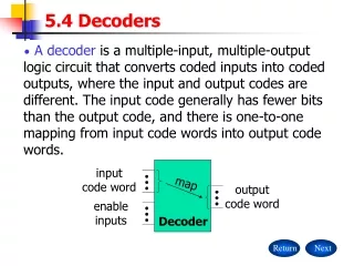
Decoder: input code word, enable inputs, mapping to output code word
2-to-4 decoder: EN=1, I0=1, I1=0 activates Y1
Signal naming conventions 74x138 3-to-8 decoder G must be 100 to decode
Logic diagram 74x138 3-to-8 decoder
Truth table 74x138 3-to-8 decoder
5-to-32 Decoder cascading 74x138 3-to-8 decoders
G input to construct a 4-to-16 decoder using74x138 3-to-8 decoder
ENCODERS 6.5
Binary Encoders For n=3 2n=8 Input: I0, I1, … I7 Output: Y0, Y1, Y2 If IY=1 Y2Y1Y0=Y
Request encoder Only one input signal can be active at a time
Logic equations for a priority encoder H7 = I7 H6 = I6•I7’ H5 = I5•I6’•I7’ … Then the outputs are generated bybinary encoding of the H signals(only one of which can be High).
Logic symbol for a generic8-input priority encoder If I5, I2, and I0 are on, the output is 101
74x148 8-Input Priority Encoder • Active-low I/O • Enable Input • “Got Something” • Enable Output
Truth table for a 74x148 8-input priority encoder Inverted inputs: only highest LOW bitmatters
Truth table for a 74x148 8-input priority encoder Note Got Something (GS) and Equal (EQ_L) outputs.
Cascading Priority Encoders 32-input priority encoder
Summary Decoders map an n-bit signal to one of 2n signals. Encoders map one of 2n signals to an n-bit signal. Some encoders can only have one input line active. Priority encoders can have several. Most MSI modules have additional control I/O lines. Many eight-bit SSI devices can be combined for wider words. Next: Three-state Devices,Multiplexers and Demultiplexers, EXORs
Comparators • A comparator is a circuit which compares two input words and produces 1 if they are equal and 0 if they are not equal. • Based on the Exclusive-OR gate, which returns 0 if its inputs are equal and 1 if they are unequal. • A NOR gate decides whether to return 1 for equality or 0 for inequality.
Comparators A B EQL LES GTR A2 A1 B2 B1 A=B A<B A>B 0 0 0 0 1 0 0 0 0 0 1 0 1 0 0 0 1 0 0 1 0 0 0 1 1 0 1 0 0 1 0 0 0 0 1 0 1 0 1 1 0 0 0 1 1 0 0 0 1 (NB Bits reversed) 0 1 1 1 0 1 0 (A2 & B2 are LSBs) 1 0 0 0 0 0 1 1 0 0 1 0 1 0 1 0 1 0 1 0 0 1 0 1 1 0 1 0 1 1 0 0 0 0 1 1 1 0 1 0 0 1 1 1 1 0 0 0 1 1 1 1 1 1 0 0