Download
1 / 18
180 likes | 338 Views
TEC X5 Setup (1). 1 Front + 1 Back petal, fully equipped (28 modules F.P. + 23 modules B.P. + AOH + DOHM) Petal assembly IPN-Lyon (F.P.), RWTH-Aachen I (B.P.) Constitutes one full TEC control ring Full optical link with optical PMC-FEC (VME-FEC will be added in coming days)

E N D
TEC X5 Setup (1) • 1 Front + 1 Back petal, fully equipped (28 modules F.P. + 23 modules B.P. + AOH + DOHM) • Petal assembly IPN-Lyon (F.P.), RWTH-Aachen I (B.P.) • Constitutes one full TEC control ring • Full optical link with optical PMC-FEC (VME-FEC will be added in coming days) • 2 x FED9U in same crate (68 chans F.P., 56 chans B.P.)
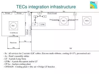
TEC X5 Setup (2) • Petals placed back-to-back in insulated cold / dark box • Series cooling loop: B.P. -> F.P. -> copper cooling plate • Cooling plant 500 W @ -20C • Temp. / Humidity monitoring + DCU information being read
Installation experience • Mechanical installation, cabling, etc.: 2 days • FEC communication established immediately • First Landau: 4 days after arrival • Approximate strip statistics after installation at X5 - 1 dead readout channel (256 strips) not included: • Dead: 99 / 31488 -> 0.31 % • Noisy: 8 / 31488 -> 0.03 % • (No loss of strips after 800 km car transport Aachen to CERN) • One module with HV short
Early Results • FED9U works • Internal pedestal + common mode noise subtraction • Zero suppression being studied – first results encouraging • ENC noise close to expected: • Estimated independently using (a) calibration pulses (b) signal peak (assume 22,000 e- in 320 micron Si) • Fit with known detector capacitance gives: ENC = 511 + 25C (C ranges 11 pF R1 to 26 pF R7)
ENC noise from cal runs Note: online data, very rough analysis!
Selected Landaus, Peak Mode V = 300 V
S/N vs Ring (Peak Mode) V=300 V
FED Zero Suppression Note: Problem with internal FED common mode subtraction for these runs
First results at low temp. Temperature of sensor leg = -5 °C approx. (Compare S/N room temp = 18)
Problems • One dead R5 readout channel (256 strips) • HV short on FP stereo module 2.4 • BP 2.1 does not receive HV • One R5 module with very low noise (broken bonds?) • High CMN on R5 module associated with noisy strip
To Do this Week • No beam • Improve thermal contact of T and H sensors on modules • Improve cooling circuit and thermal isolation of box • Logging of DCU values • Commission VME FEC • Try higher fast control speeds • Pulse shape studies (cal runs) • Repeat bad strip study • Finalize installation of slow ctrl / interlocks