Download
1 / 15
170 likes | 350 Views
Arduino-BOT Lecture #2 EGR 120 – Introduction to Engineering. 1. Servos and the Arduino -BOT. Board of Education Shield. Continuous-rotation servo. Typical signal used to turn the servo. 1.5 ms. 1.5 ms. Stop. 20 ms. References :

E N D
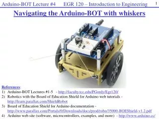
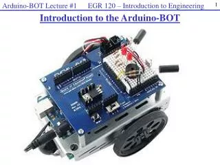
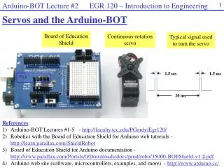
Arduino-BOT Lecture #2 EGR 120 – Introduction to Engineering 1 Servos and the Arduino-BOT Board of Education Shield Continuous-rotation servo Typical signal used to turn the servo 1.5 ms 1.5 ms Stop 20 ms References: 1) Arduino-BOT Lectures #1-5 - http://faculty.tcc.edu/PGordy/Egr120/ 2) Robotics with the Board of Education Shield for Arduino web tutorials - http://learn.parallax.com/ShieldRobot 3) Board of Education Shield for Arduino documentation - http://www.parallax.com/Portals/0/Downloads/docs/prod/robo/35000-BOEShield-v1.2.pdf Arduino web site (software, microcontrollers, examples, and more) - http://www.arduino.cc/
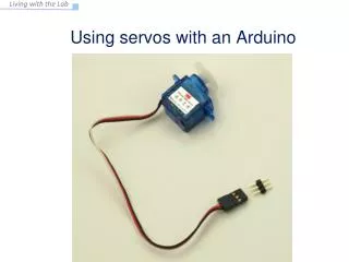
Arduino-BOT Lecture #2 EGR 120 – Introduction to Engineering 2 • Servo - A servo is a single device that contains: • Motor • Gearbox that gears down the motor to provide slower speeds (than most motors) and higher torque (power to turn). • Built-in electronics such that the motor position or speed can be controlled by a series of pulses. The servo is powered using 5V (4.8 – 6.0 V)
Arduino-BOT Lecture #2 EGR 120 – Introduction to Engineering 3 Connecting Servos to the BOE Shield for Arduino We could use digital outputs to control the servos, but servo ports have been conveniently provided for plugging in the servos. Servo ports
Arduino-BOT Lecture #2 EGR 120 – Introduction to Engineering 4 Servo port jumper The servos can be powered either by 5V or by Vin, which is the unregulated battery voltage (perhaps 7.5V for 5 AA batteries). Our servos are rated to use 4.8 – 6.0V, so the jumper should be set to 5Vas indicated below.
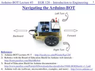
Arduino-BOT Lecture #2 EGR 120 – Introduction to Engineering 5 • Plugging in the servos • The servos should be plugged in as shown below. If they are already plugged, in check them to be sure that they are correct. • Be sure that the black wire is in the appropriate position. • Be sure that: • The LEFT servo is plugged into Port 13 • The RIGHT servo is plugged into Port 12 (the ball is at the rear ). To RIGHT Servo To LEFT Servo
Arduino-BOT Lecture #2 EGR 120 – Introduction to Engineering 6 • Types of servos • There are two types of servos: • Unmodified servos– the servo can turn over a certain range, such as 180º • Used commonly on RC (radio control) cars and airplanes for steering, moving control flaps, etc. • Available in hobby stores, such as Hobbytown USA or Debbie’s RC World • The servo position is controlled by varying the pulse width of a control signal (see below) • Modified servos • Servo has been modified internally so that it will turn continuously. • Commonly used as a drive motor for a robot, such as the Arduino-BOT. • The servo speed is controlled by varying the pulse width of a control signal (see below) Pass around servos of each type in class 0 degrees 90 degrees 180 degrees 0º 180º 90º Full speed CW Stop Full speed CCW CW Stop CCW
Arduino-BOT Lecture #2 EGR 120 – Introduction to Engineering 7 Servo Signals Servos are typically operated using pulse-width modulation, where they receive control signals to make them turn. The pulse width varies from about 1.3ms to about 1.7ms (or 1300 us to 1700 us) and the pulses are separated by 20ms. These values are set by the manufacturer. Varying the pulse as described can be used to make a continuous servo turn at any speed between full speed CW to full speed CCW (typically about 50 rpm max). The pulses must continue to keep the servo moving. If the pulses stop, the servo stops. 1.3 ms 1.3 ms Full speed CW 20 ms Stop 1.5 ms 1.5 ms 20 ms 1.7 ms 1.7 ms Full speed CCW 20 ms
Arduino-BOT Lecture #2 EGR 120 – Introduction to Engineering 8 Controlling servos with the Arduino Sending a series of pulses to a servo is similar to turning ON and OFF and LED. Recall our earlier example below where an LED on digital pin 13 turns ON for 0.5 s and OFF for 0.5 s. The LED will blink indefinitely. 0.5 s LED ON LED OFF 0.5 s
Arduino-BOT Lecture #2 EGR 120 – Introduction to Engineering 9 Controlling servos with the Arduino The code on the previous page can be adjusted to make a servo on servo port 13 move full speed CW. 1.3 ms 1.3 ms Full speed CW 20 ms
Arduino-BOT Lecture #2 EGR 120 – Introduction to Engineering 10 • A better way to control servos • The Arduino programming language includes a better way to control servos. It involves using the Arduino servo library. • The library is actually a class. Using a class allows you to declare objects and use member functions that work with those objects. Programming with classes is called object-oriented programming. You will learn more about object-oriented programming using C++ in EGR 125. • Useful Arduino servo library instructions: • #include <servo.h> // include the servo library (class) • Servo servoLeft, servoRight; // declare two new objects in class Servo. Any • // name is OK, but servoLeft is descriptive • servoLeft.attach(13); // associate the left servo with digital • // pin 13 (Servo Port 13) • servoLeft.writeMicroseconds(1300) // send a pulse train continuously to • // servo port 13 with a high time of • // 1.3ms & a low time of 20 ms (default) • servoLeft.detach(); // disassociate the left servo from current port • // this will stop the servo
Arduino-BOT Lecture #2 EGR 120 – Introduction to Engineering 11 A better way to control servos So, the previous example used to turn a servo full speed CW on port 13 can be re-written as:
Arduino-BOT Lecture #2 EGR 120 – Introduction to Engineering 12 Starting and stopping a servo The previous example was used to turn a servo continuously. Suppose that we wanted it to only turn for 10 seconds? One way to accomplish this is to turn it on, wait for 10 s, and then turn it off. Notes: The argument for the delay( ) function is an unsigned long int which can have a value from 0 to 4,294,967,295 so the max delay is 4,294,967,295 ms = 4,294,967.295 s 8.2 years We will use the delay( ) function for delays of several seconds in our programs, but this is typically discouraged as most Arduino functions will be halted during the delay (such as reading sensors).
Arduino-BOT Lecture #2 EGR 120 – Introduction to Engineering 13 Servo speed data In Team Assignment #2 we will determine exactly how fast each servo on the Arduino-BOT will turn for each pulse width. This will allow us to: Select the proper pulse width for different speeds Match the two servos so that they turn at the same rate Recall that in order to make the servo turn at any speed between full-speed CW and full-speed CCW, the pulse width should vary from 1.3ms to 1.7ms or from 1300 us to 1700 us. So the corresponding commands are: servoRight.writeMicroseconds(1300); // full-speed CW servoRight.writeMicroseconds(1700); // full-speed CCW
Arduino-BOT Lecture #2 EGR 120 – Introduction to Engineering 14 Example: Left wheel servo test Each servo is a little different from the next, so in Team Assignment #2, each group will test their two servos by varying the pulse width gradually in order to determine the servos’ speed and direction for each value of pulse width. A table somewhat like the one on the right will be determined for each servo. Teams will count the number of wheel revolutions for 15 s and multiply by 4 to get revolutions per minute (rpm). Vary the pulse width from 1300 to 1700 and count the wheel revolutions
Arduino-BOT Lecture #2 EGR 120 – Introduction to Engineering 15 Team Assignment #2 In Team Assignment #3 you will record the number of RPM’s for each pulse width for each servo. You will also graph the information (similar to the graphs shown below). Your data will be used in later labs to determine which pulse widths are needed to make your Arduino-BOT move around a track.