Download
1 / 22
220 likes | 352 Views

E N D
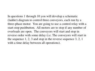
In questions 1 through 10 you will develop a schematic (ladder) diagram to control three conveyors, each run by a three-phase motor. You are going to use a control relay with a start-stop pushbutton. All motors are to stop if any number of overloads are open. The conveyors will start and stop in reverse order with some delay (i.e. The conveyors will start in the sequence 1, 2, 3 and stop in the reverse sequence 3, 2, 1 with a time delay between all operations).
1. Draw a schematic of a rung to provide start-stop pushbutton control of a control relay CR. Provide positive overload protection for 3 motor starters.
1. Draw a schematic of a rung to provide start-stop pushbutton control of a control relay CR. Provide positive overload protection for 3 motor starters. NOTE: Identify time-delay relays as: DOE - delay on energized DODE - delay on de-energized Identify timing contacts as: NOTC - N.O. Timed Closed NOTO - N.O. Timed Opened NCTC - N.C. Timed Closed NCTO - N.C. Timed Opened
1. Draw a schematic of a rung to provide start-stop pushbutton control of a control relay CR. Provide positive overload protection for 3 motor starters. NOTE: Identify time-delay relays as: DOE - delay on energized DODE - delay on de-energized Identify timing contacts as: NOTC - N.O. Timed Closed NOTO - N.O. Timed Opened NCTC - N.C. Timed Closed NCTO - N.C. Timed Opened
2. Add a second rung to start conveyor 1 (M1) as soon as the start button is pushed. Energize timer TR1 coil at the same time that coil M1 is energized.
2. Add a second rung to start conveyor 1 (M1) as soon as the start button is pushed. Energize timer TR1 coil at the same time that coil M1 is energized.
3. Add another rung (rung 3) to start conveyor 2 (M2) 10 seconds after conveyor 1 starts. Use an on-delay contact off of timer TR1 to start M2. Include a second timer TR2 in parallel with coil M2.
3. Add another rung (rung 3) to start conveyor 2 (M2) 10 seconds after conveyor 1 starts. Use an on-delay contact off of timer TR1 to start M2. Include a second timer TR2 in parallel with coil M2.
4. Add a fourth rung to start conveyor 3 (M3) 10 seconds after conveyor 2 starts. Control this conveyor using an on-delay contact on timer TR2.
4. Add a fourth rung to start conveyor 3 (M3) 10 seconds after conveyor 2 starts. Control this conveyor using an on-delay contact on timer TR2.
5. Add a rung to provide a third time delay relay (DODE) which is energized whenever control relay CR is energized. Call this timer TR3.
5. Add a rung to provide a third time delay relay (DODE) which is energized whenever control relay CR is energized. Call this timer TR3.
6. Modify rung 4 to include an off-delay contact from timer TR3 so that 10 seconds after the stop is pushed (and CR is de-energized) that the contact will open therefore shutting down conveyor 3.
6. Modify rung 4 to include an off-delay contact from timer TR3 so that 10 seconds after the stop is pushed (and CR is de-energized) that the contact will open therefore shutting down conveyor 3.
7. Draw rung 6 to provide control of a new timer (DODE) TR4 from an auxiliary contact on relay CR.
7. Draw rung 6 to provide control of a new timer (DODE) TR4 from an auxiliary contact on relay CR.
8. Modify rung 3 to include an off-delay contact from timer TR4 which will stop conveyor 2 (M2) 20 seconds after the stop button is pressed.
8. Modify rung 3 to include an off-delay contact from timer TR4 which will stop conveyor 2 (M2) 20 seconds after the stop button is pressed.
9. Draw a final rung (7) to energize timer (DODE) TR5 whenever relay CR is energized.
9. Draw a final rung (7) to energize timer (DODE) TR5 whenever relay CR is energized.
10. Modify rung 2 by replacing the NO CR contact with an off-delay contact that will turn conveyor number 1 off 30 seconds after relay CR is de-energized using timer TR5.
NOTE: In question 2 a normally-open CR contact was drawn to control starter M1. With this question the NO CR contact is replaced with a NOTO timed contact Controlled by timing relay TR5. 10. Modify rung 2 by replacing the NO CR contact with an off-delay contact that will turn conveyor number 1 off 30 seconds after relay CR is de-energized using timer TR5.