Download
1 / 41
410 likes | 608 Views
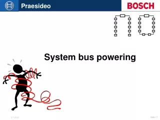
Serial Powering of Silicon Strip Detectors at SLHC Marc Weber, Giulio Villani, M. Tyndel (RAL) with Anu Tuonnonnen and Robert Apsimon. Could this scheme be better?. Independent powering. PS. PS. PS. PS. PS. PS. PS. PS. PS. Power in Power out. PS. PS. Powering schemes.

E N D
Serial Powering of Silicon Strip Detectors at SLHCMarc Weber, Giulio Villani, M. Tyndel (RAL)with Anu Tuonnonnen and Robert Apsimon
Could this scheme be better? Independent powering PS PS PS PS PS PS PS PS PS Power inPower out PS PS Powering schemes
How to power a SLHC tracker ? Many unknowns, but power will be a major challenge and affects cooling, material budget, packaging and moreFocus of this talk is on silicon strip sensors. There is earlier powering stuff for ATLAS pixels by Bonn university groupKnownSCT: up to 160 m long cables, cable resistance up to ~ 3.5 ΩSCT: power efficiency 50%, 25 kW module power; 50 kW totalEstimate (assuming lower voltages, similar current and cable resistance)SLHC: power efficiency 20%, if 50 kW modules power 400 kW totalThis is a power station not a tracker !
Why independent powering fails at SLHC ? • Don’t get 5 or 10 times more cables in • Power efficiency is too low (50% SCT 20% SLHC) • Material budget: 0.2% or R.L. per layer (barrel normal incidence) 1% or 2% SLHC • Packaging constraints • Each reason by itself is • probably sufficient for a • No-No
M2 M1 M3 M2 M1 M3 M2 M1 M3 Alternatives to IP Analog and digital voltage IP Serial powering and parallel power bus with DC-DC conversion Note: Parallel powering without DC-DC conversion is problematic due to low power efficiency and large IR drops Constant current for both analog and digital power SP PP with DC-DC conversion
How does SP work? • Four elements • Current source • Shunt regulator and power device (digital power) • Linear regulator (analog power) • AC or opto-coupling of signals
Regulators 8V 4V 4V 0V Chain of modules at different voltages Chips on a module are connected in parallel (as usual) analog ground, digital ground and HV ground are tight together for each module (as usual) floating HV supplies
AC LVDS coupling Simplified AC coupling diagram All but one module are on different potential than DAQ LVDS buffers are at the potential of the receiving unit (DAQ power for data; module power for clock/control) Opto-decoupling is an alternative
M2 M1 M3 M2 M1 M3 Advantages of serial powering • Reduce number of cables by factor 2x2n/2=2n(even more if counting sense wires) • Huge increase of power efficiency over IP as Vdd goes down: [1+x]/[1 + x/n] x = cable IR/Vdd • material reduction • cost savings (cables and PS) Same benefits for DC-DC conversion Combining analog and digital cables SLHC Vdd=1V ~1+x “SCT” Vdd=4V
Perceived disadvantages of SP “ Only a physicist can be crazy enough to try this!” • Noisy; oscillations; interference between modules probably not main difficulty • Risky; can lose all modules due to single-point failure • Much less risky than one might think • Loss of control over individual modules • important constraint that can be addressed to some extent • Grounding and shielding of densely packaged extended system • is part of stave R&D
Serial powering interface board with regulator and AC coupling Commercial components; connectors SCT modules are untouched; standard SCT PS is not used
Schematic of Shunt regulator Simple but effective design Will be integrated in custom RDIC or dedicated ASIC in the future (ATLAS pixel chip contains active circuitry already)
Shunt regulator circuitry • Linear regulator circuitry • M • O • D • U • L • E • D • A • Q • LVDS buffer circuitries SP interface board in more detail • Shunt regulator and power transistor; analog regulator • 3 x AC LVDS coupling (clock/control/data) Large area prototype for small board (see Carl’s talk)
Hybrid • SSPPCB • ABCD3TV2 We can make this much smaller • 2+2 layer PCB; 38 x 9 mm2 (this is a PCB for cost reasons) • Further shrinkage if SP integrated into hybrid and if most circuits elements integrated into readout ICs • Estimated extra hybrid floor area due to SP: ~10%
Hybrid noise with and without SP board RAL SP LBNL IP This is “serial powering” of one hybrid (4-chip LBNL hybrid) Bare hybrid measurements are most sensitive SP noise performance is excellent regulators work fine
Noise performance of 6 SCT modules Precise measurements; noise performance of SP is excellent
A closer look at the same data Gain ENC Channel Channel Combining two data streams (link0 and link1) saves space don’t read out chip 7 SP and IP noise and gain are very similar The same is true for the other 5 modules (not shown)
Noise distribution of one of the 6 SCT modules Noise performance of SP is excellent
Noise injection Principle: superimpose a current modulation of 15 mA to 1.6 A current; scan through a frequency range from Hz to 40 MHz; measure module noise
Noise injection: SP with 6 SCT modules <ENC> Frequency [Hz] No significant increase in noise Note that coupling of noise between modules through power line is not possible conservation of charge/current!
Is serial powering to risky? Risk = (# of power connections) x (probability of a failure) x (# of modules lost per failure) I am sure there are other ways to define risk, but this is instructive • Risk of module loss due to single-point failures for IP and SP • Over current protection through shunt regulator design • Protection by operating SR in parallel
Distribution Board Module 1 Module 2 Module n Power supply Digital PS 1 Risk comparison: IP vs SP Analog PS 1 Distribution Board Module 1 Module 2 Module n Digital PS 2 IP Analog PS 2 Digital PS n Analog PS n SP SP: one broken connection loses n modules however, much less cables less connections
Risk comparison Risk ratio (SP/IP) Make your own choices for values of a,b, and c Mine are here … # of modules Risk due to breaking bonds/connections is larger for SP, but less than one might think Risk increases ~ number of modules/4 Build in increased redundancy
Architecture choices: single vs. multi- SR arrangement RDIC RDIC RDIC RDIC Single SR and LR for 2 chips 2parallel SR and LR for 2 chips • Remember, in SP you have to fight opens! (in PP, shorts) • Parallel SR and LR arrangement is safer(SR and LR are part of RDIC) • Failure of one power transistor does not kill all modules • Can also use register to set voltages on chip
Overcurrent protection Power transistor is weakest point of SR regulator It has to stand full current in case of a module open risk of burn out Protect against this by automatically reducing SR voltage in case of overcurrent condition Simplified diagram for illustration of overcurrent protection
AC LVDS coupling We use two different schematics Command/data signal: feed-back resistor between input and output of LVDS buffer (value should be high enough to allow for multi-drop configurations) Clock: LVDS buffer input is pulled to buffer ground ( non-standard common mode level) Clock Command
AC LVDS coupling Tested AC LVDS coupling with dedicated test circuits for large range of duty cycles and frequencies ; this is work in progress 120 MHz 40 MHz 1 MHz This works just fine in practice; conventional wisdom is that you should not do it this way (no DC balanced protocol; no 0V common-mode) We will find out why it works… 1 MHz
Future R&D program on powering schemes Goal: be ready for implementation of advanced SP and DC-DC conversion PP systems in a realistic module assembly in ~ 3 years Can distinguish three phases: Generic studies(as presented here and in Carl’s talk) to identify crucial features and challenges “easy”, affordable, “fun” Develop radiation-hard custom electronics (ABC_Next chip); build and test systems with large number of modules significant effort, serious engineering Implemention of power distribution schemes on advanced supermodule prototypes “service”, crucial to establish supermodule electrical performance
What we have learnt so far • Noise performance is excellent; expect SP systems to be less noisy than alternatives; IR drops don’t matter for one • Risk of failure is bigger than for IP but much smaller than naively expected; SP/IP risk ~ n/4; can use fraction of space gains to buy robustness; protect power transistor • Power efficiency is hugely improved (depending on x=IR/V); 20% (IP) -> 80% (SP) can save >100 kW of cable losses easily; power consumption of SP circuitry is small, dominated by excess current in power transistor • Need to emphasize voltage adjustment and feed-back from individual modules (slow control)
Outlook It unusual to gain such significant factors in a technology as mature as silicon detectors SP is challenging but I believe we can make it work If you are sceptical about these concepts, remember that we need to innovate. Without new powering schemes, we will simply not get any SLHC tracking detectors Last, but not least: this not only of interest for SLHC. ILC tracker or non-silicon detectors might benefit as well
Same board used with bare hybrid DAQ support card Hybrid S P P C B
Iin Vout Comp Vcout Comparator Vin- Comparator Vin+ First simulation results
A look at material issues • naively extrapolating from an SCT to an SLHC layer assuming 5 times more channels, we get (one layer, barrel, normal impact): Material budget will explode at SLHC without innovations in powering, packaging, and cooling *crude estimate; no innovation too big !
Cables Barrel Discs Interaction point A look at material issues • services in ATLAS SLHC tracker would still run in gap between barrel and end cap detectors • in current SCT, particles cross (0.1 to 0.45%) x √2 of R.L. of cables in gap alone (dep. on polar angle) a 5 or 10-fold increase of these numbers is prohibitive Generic ATLAS SLHC Tracker Configuration
Power efficiency M2 M1 M3 M2 M1 M3 M2 M1 M3 Let’s look at 4 different powering set-ups for a stave with n modules • Each module is independently powered (IP scheme) • Power busses on stave serve modules in parallel (PP) • Parallel, but with DC-DC conversion (DCP) … • Modules are chained in series (SP) Definitions: Module current and voltage: I, V Cable resistance (including return): R • power consumed by stave with n modules is always: n I V • power wasted in the cable varies with powering scheme
Power efficiency Ignoring effects of regulators and other complications, get easy dependencies Efficiency decreases with increasing R, I and decreasing V Significant advantage for serial powering and DC-DC, even for small numbers of modules n and small gain g