Download
1 / 19
200 likes | 266 Views
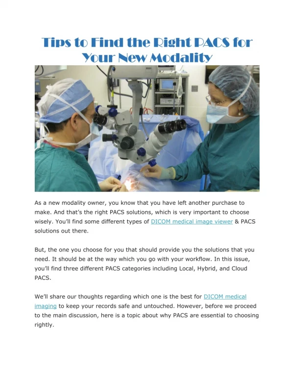
This article provides an overview of Supplement 145, focusing on whole slide imaging in DICOM. It covers topics such as image resolution comparable to optical microscopy, rapid image access, multiple focal planes, and multi-spectral imaging. The text delves into tiling and multi-frame encoding, sparse tiling, navigation and zoom access, hierarchical pyramids, optical paths, and multi-spectral imaging. It also explores standard DICOM mechanisms for WSI annotation, color presentation states, segmentation, structured reporting, and real-world value mapping.

E N D
Whole Slide Imaging in DICOM Harry Solomon GE Healthcare
WSI Supplements • Two DICOM Supplements developed by WG-26 Anatomic Pathology • Supplement 145: Whole Slide Imaging • Adopted August 2010 • Supplement 122: Specimen Module • Adopted June 2008
The Whole Slide Problem • Need image resolution comparable to optical microscope • Need image access as rapid as microscope (pan, zoom, focus) Yukako Yagi– UPMC
Digital slides are huge • Sample size ~ 20mm x 15mm • Resolution of .25 μm/pixel (40X objective) • 80,000 x 60,000 pixels = 4.8 Gp • 24-bit color = 14.4 GB / slide • 40:1 compression = only 360 MB / typical slide Unless • Larger specimen • Higher resolution (100X objective) • Multiple focal planes • Multi-spectral imaging (16-bit / band) And • A typical study may be 10 slides
Fixed Header Dimension data Pixel data Per-frame header Sup 145 Tiling and Multi-frame encoding • Whole Slide Image divided into tiles • Each tile encoded into a frame of multi-frame image object • Per-frame header givesspatial location for each tile: X, Y, and Z (focal plane) Multiple focal planes Multi-frame image object
Z-planes (focal planes) • Z-planes are identified as nominal physical height of image focal plane above reference surface (μm) • Z-plane information is used for relative spatial positioning of image planes, and nominal inter-plane distance • An image plane may track variable specimen thickness / surface contour, but only one Z-value used ↑ Z Cover slip ↑ Z Specimen Slide substrate (glass)
Z planes may track curved surface Z plane 1 Z plane 2 Z plane 3 Z plane 4 Tile 1 Tile 2 Tile 3 Tile 4 Tile 5 Tile 6 Tile 7 Tile 8 Viktor Sebestyén Varga – 3DHISTECH Ltd.
Total Pixel Matrix Total Pixel Matrix Origin • Total pixel matrix origin at top left hand corner of imaged volume • Frame (tile) rows and columns align with total pixel matrix rows and columns • Frames limited to 216 columns and rows each • Total pixel matrix limited to 232 columns and rows Columns → Rows ↓ Frame Pixel Matrix Origin Total pixel matrix coordinates used for frame location and for annotation
Sparse tiling • Slides may have substantial area with no specimen • Empty tiles may be absent from multi-frame image
Access: Navigation and Zoom Need to rapidly access: • High resolution image of small areas • Facilitated by tilling • Low resolution image of whole slide • For overview and navigation • Intermediate resolutions • Smooth zooming Lower resolution images may bepre-computed • Hierarchical pyramid • May add ~ 33% to size of data
Tiling and multi-frame at all hierarchical levels Single frame image Thumbnail Image Multi-frame image (single object) Intermediate Image Multi-frame image (single object)may include multipleZ-planes, color planes Baseline Image All image objects typically in 1 DICOM Series
Localizer image “flavor” • Thumbnail image (single frame) plus navigation links to each frame at each resolution • Each tile of other resolution images has its corresponding area identified in thumbnail • Full description of target tiles • Object Unique ID and frame number • Resolution • Z-plane, color • Multiple target frames can overlap • Different resolution, Z-plane, color, etc. • Presentation and any interactive behavior is not defined in standard
Optical paths • Each combination of light source, lenses, illumination method, detected wavelengths, etc. used in a scan is an optical path • Three primary mandatory attributes: • Illumination color or wavelength • Illumination method (e.g., transmission, epifluorescence , darkfield, differential interference contrast) • Detection color • Additional optional attributes for lenses, filters, prisms, etc. • Examples: • Full spectrum light, transmission, RGB color sensors • UV excitation, epifluorescence, 535 nm emission filter, monochrome sensor Illumination Method Illumination Filters Lens Lens Filters Sensor
Multi-spectral imaging • Typical color image stored with RGB or YBR photometric interpretation • 3 color values / pixel • Multi-spectral image stored with MONOCHROME photometric interpretation • 1 color value / pixel / color plane • Multiple color planes – may be stored in single image object • Each frame references its optical path in per-frame header 3 x 8-bit RGB n x 16-bit multi-spectral
Standard DICOM mechanisms for annotation of WSI • Color Presentation State • Displayed Area Selection relative to WSI total matrix • Graphic and text annotation with sub-pixel location resolution, even with 8M columns or rows • Segmentation • Can be created pixel-by-pixel against selected frames of original image • 1-bit/source-pixel, or 8-bits/source-pixel • Display of segmentation implicitly invokes blending with source image • Structured Reporting • Captures measurements, clinical observations, analyses, and findings • Real World Value Mapping • Specifies a mapping of the stored pixel values of images into some real world value in defined units • Allows quantitative methods with monochrome images (original or derived)
Interpretation Worklist by accession Pathology order Slide preparation history data LIS / APLIS Specimen accessioning data Modality Worklist Query by slide barcode Imaging task w/ slide preparation history data Imaging task completion w/ list of imagesand specimen IDs Images Images Images w/slide prep history PACS Images – X-ray, U/S, optical, etc. Anatomic Pathology Imaging Workflow Slide preparation Workstation Gross specimen accessioning Whole Slide Scanner Surgical or biopsy procedure
Sup 122 Specimen Module • Support for pathology lab workflow, specimen-based imaging • Gross specimens, blocks, vials, slides • Image-guided biopsy samples • Specimen Module at image level of hierarchy • Identification, processing history (especially stains applied) • Modality Worklist can convey Specimen Module • Enables automated slide scanning devices to fully populate image header • Processing history can be used to set up acquisition (based on stain) • Modality Performed Procedure Step identifies imaged specimen • Allows LIS/APLIS to track images for specimens
Specimen Imaging Information Model Disambiguates specimen and container Container is target of image Container may have more than one specimen Specimens have a physical derivation (preparation) from parent specimens When more than one specimen in an imaged container, each specimen is distinguished (e.g., by position or color-coding) Basic DICOM Information Model
Enabling Transformation to Digital Pathology • Supplements 145 and 122 establish the foundation for a true market for digital imaging in anatomic pathology • Comparable in importance to the introduction of DICOM to radiology in 1993 • Enables quantitation and collaboration • In the next 5-10 years, we should expect a profound transformation of pathology from a highly manual process to a digital workflow • The use of the DICOM Standard across radiology, pathology, surgery, and radiation therapy opens the door to truly integrated data from screening to biopsy to diagnosis to treatment