BOE-BOT
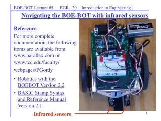
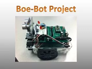
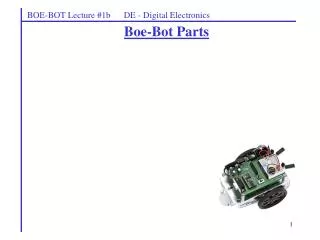
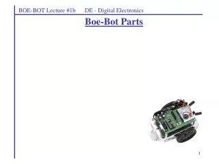
BOE-BOT. By: Jonathan Baker Gabby Garcia. BOE-BOT. Servo motors to control each wheel independently Castor wheel in rear for stability Aluminum Chassis BASIC Stamp 2 microcontroller SayIt Module IR Sensors Runs off 4 AA batteries. Rear view of BOE-BOT. Front view of BOE-BOT.

BOE-BOT
E N D
Presentation Transcript
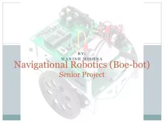
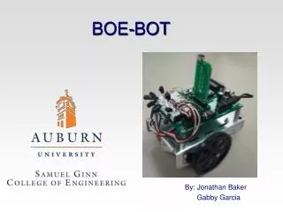
BOE-BOT By: Jonathan Baker Gabby Garcia
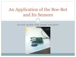
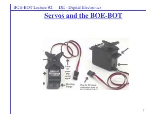
BOE-BOT • Servo motors to control each wheel independently • Castor wheel in rear for stability • Aluminum Chassis • BASIC Stamp 2 microcontroller • SayIt Module • IR Sensors • Runs off 4 AA batteries Rear view of BOE-BOT Front view of BOE-BOT
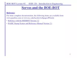
BASIC Stamp 2 • BASIC Stamp 2 is a 24-pin DIP • 20 MHz processor speed • 32 Bytes of RAM • BASIC Stamp 2 Editor used to write and compile program • PBASIC is language used for programming • USB to serial adapter used to transfer code to robot
SayIt Module • Parallax voice recognition 10-pin SIP module • 32 speaker dependent (SD) commands • SayIt GUI serves as interface for programming the user definable commands Front view of SayIt module Rear view of SayIt module
SayIt Module GUI • Trigger is used to make BOE-Bot listen for a command • Group 1 – 15 are SD • Wordset 1 – 3 are SI Speaker Dependent Speaker Independent
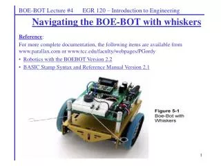
Infrared Detectors • 4 pairs of IR detectors • IR LEDs emit signal at 940 nm at a rate of 38.5 kHz • Frequency of signal is specified in the code • IR receivers have electronic filter that only allows signals with this frequency IR Detector Circuit
Infrared Detector • Heat shrink used as shields to focus the IR signal • For near sighted robot use larger resistor value to decrease current • Opposite for a far sighted robot Actual IR Detector Circuit
Demonstration of Project YouTube Link: BOE-Bot Demonstration