ELECTRICAL COMPONENTS
ELECTRICAL COMPONENTS. CHAPTER 3. Circuit Protection. Circuit Protection (Page C52 ). Types of Fused Protection. How to pull them. Fuses (Page C52). Auto-fuse (blade type and Color coded) Mini-fuse Maxi-fuse. A. TEST HOLES B. REMOVAL. Maxi-fuses. C52.

ELECTRICAL COMPONENTS
E N D
Presentation Transcript
ELECTRICAL COMPONENTS CHAPTER 3
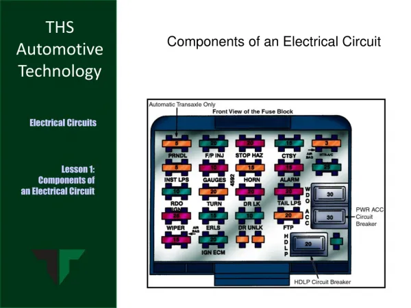
Circuit Protection (Page C52 ) • Types of Fused Protection How to pull them
Fuses (Page C52) • Auto-fuse (blade type and Color coded) • Mini-fuse • Maxi-fuse A. TEST HOLES B. REMOVAL
Maxi-fuses C52 • Combination blade / cartridge • Protects main circuits • Safer than fusible link • Cover fewer circuits than a fusible link • Often in Power Distribution box
Ceramic and Glass C52 & L53 • Rated by current failure level • Three letter code for type and size • Glass style replaces ceramic • Caution in pulling
Two reasons for blowing Where do they blow? Why?
New Circuits ? • What size of fuse should I install? • Use Watts law. Watts divided by volts Page L53
FUSIBLE LINKS • Lighter gauge wire than main conductor • Covered with special insulation • Protect Main circuits • Usually under hood
C54-55 L53-54 Fusible Links Repair • Location • Circuits protected • Insulation • Visual checks • Installing a new link • 4 wire sizes smaller (4 numbers larger) • Soldering
Circuit Breaker C56 & L55 • Why circuit breakers • Styles • Deterioration
TESTING CIRCUIT PROTECTION DEVICES • Must inspect closely • Type of failure determines cause • Best to use DVOM • Do not overload circuit by installing to large of fuse or tin foil • Connections must be tight • Do not use un-fused jumper wire
Switches OPERATION Page C58-60 TESTING Page L57-58 • Controls electrical current (N.O. or N.C.) • Single-pole, single throw (SPST) • Momentary Switch • Single-pole, double throw switch (SPDT) • Ganged Switch
Relays OPERATION Page C60-61 • Electromagnetic Switches (Relays) • Two Circuits • Control Circuit • Load Circuit • Magnetic field operates contacts • Late model relays are universal
TESTING RELAYS Lab 59-60 • Can use several methods to test • Must Check both circuits • Be careful using test light if relay is operated by computer • Can bench test if needed • Some relays have schematic on them • Must be correct resistance
SOLENOIDS C61 • Electromagnetic device with a iron core • Does mechanical work • Core is moveable and does work • Can test with DVOM
C62-64 L61 STEPPED RESISTORS • Usually used to control fan motor speeds • Resistance is changed by control of switch • Controls current to change speeds • Thermal fuse
OPERATION C62-64 TESTING LAB 62 Variable Resisters • Rheostats • Two terminals • Higher current • Potentiometer • Three terminals • Lower current • Many uses for variable types C62-63 & L62
The three types of circuit defects are: • Shorts • Grounds • Opens • poor connections C75-78 L64-71
TESTING FOR CIRCUIT DEFECTS • DVOM IS BEST TO USE! • Must know circuit operation before can diagnose problem • Must know how to use equipment and which equipment to use. LAB PAGE 64 TO 71