Direct Design Method
Detailed calculation and review of a flat slab design, including panel sizes, column dimensions, and slab thickness for structural integrity.


Direct Design Method
E N D
Presentation Transcript
Direct Design Method Design of Two way floor system for Flat slab
Figure-1 shows a flat slab floor with a total area of 12,500 sq ft. It is divided into 25 panels with a panel size of 25 ft x 20 ft. Concrete strength is and steel yield strength is fy=40,000 psi. Service live load is to be taken as 120 psf. Story height is 10 ft. Exterior columns are 16 in. square and interior columns are 18 in. round. Edge beams are14 24 in. Overall; Thickness of slab is 7.5 in. outside of drop panel and 10.5 in. through the drop panel. Sizes of column capital and drop panels are shown in Fig.-1. Given data
[Problem-1] Compute the total factored static moment in the long and short directions of an interior panel in the flat slab design as shown in Fig.1.
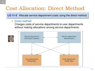
Neglecting the weight of the drop panel, the service dead load is (150/12)(7.5)=94 psf; thus wu=1.2wD +1.6wL =1.2(94) +1.6(120) =132 + 204 =336 psf
The equivalent square area for the column capital has its side equal to 4.43 ft; then, using Eq.1, with Ln measured to the face of capital (i.e., equivalent square), So far as flat slabs with column capitals are concerned, it appears that the larger values of 395 ft-kips and 292 ft-kips should be used because Eq.8 is specially suitable; in particular, ACI states that the total factored static moment shall not be less than that given by Eq.1.
Given data [Problem-2] Review the slab thickness and other nominal requirements for the dimensions in this flat slab design described in problem-1.
Stiffness of edge beams. • Before using Table-1, the α values for the edge beams are needed. The moment of inertia of the edge beam section shown in Fig.2 is 22,9000 in4. Thus the α value for the long edge beam is Fig.-2
Stiffness of edge beams. The moments of inertia Ib and Is refer to the gross sections of the beam and slab within the cross-section. ACI permits the slab on each side of the beam web to act as a part of the beam, this slab portion being limited to a distance equal to the projection of the beam above or below the slab, whichever is greater, but not greater than four times the slab thickness, as shown in Fig.
In which where h = overall beam depth t =overall slab thickness bE =effective width of flange bw = width of web
and for the short edge beam, it is These values are entered on Fig.3. (b) Minimum slab thickness using Table-1. The long and short clear spans for deflection control are: Ln = 25-4.43 = 20.57 ft; Sn = 20-4.43 = 15.57 ft. From which
Table-1 Minimum thickness of slab without interior beams *For fy between 40 and 60 ksi, min. t is to be obtained by linear interpolation.
For fy=40 ksi, a flat slab with drop panel, and α = smaller of 4.34 and 5.42, Table-1 gives For both exterior and interior panels. • Nominal requirement for slab thickness. • The minimum thickness required is, from part (b), 6.17 in. The 7.5 in. slab thickness used is more than ample; 6.5 in. should probably have been used.
(d) Thickness of drop panel. Reinforcement within the drop panel must be computed on the basis of the 10.5 in. thickness actually used or 7.5 in. plus one-fourth of the projection of the drop beyond the column capital, whichever is smaller. In order that the full 3-in. projection of the drop below the 7.5 in. slab is usable in computing reinforcement, the 6 ft 8 in. side of the drop is revised to 7 ft so that one-fourth of the distance between the edges of the 5-ft column capital and the 7-ft drop is just equal to (10.5 - 7.5) = 3 in.
Given data [Problem-3] For the flat slab design problem-1, Compute the longitudinal moments in frames A, B, C and D as shown Fig.-1, 4 & 5.
Longitudinal moments in the Frame. The longitudinal moments in frames A, B, C, D are computed using Case 4 of Fig.23(DDM) for the exterior span and Fig.19(DDM) for the interior span. The computations are shown in Table-1 and the results are summarized in Fig.4&5.
Check the five limitations (the sixth limitation does not apply here) for the direct design method. These five limitations are all satisfied. • Total factored static moment M0. Referring to the equivalent rigid frames A, B, C, and D in Fig. 4&5, the total factored static moment may be taken from the results previously found; thus • M0 for A = 395 ft-kips • M0 for B = 0.5(395) =198 ft-kips • M0 for C = 292 ft-kips • M0 for D = 0.5(292) =146 ft-kips
Given data [Problem-4] For the flat slab design problem-1, compute the torsional constant C for the edge beam and the interior beam in the short and long directions.
For the short or long edge beam Fig.6(a), the torsional constant C is computed on the basis of the cross-section shown in Fig.6(a). Fig.-6
The torsional constant C equals, where x = shorter dimension of a component rectangle y= longer dimension of a component rectangle and the component rectangles should be taken in such a way that the largest value of C is obtained.
Fig.-8 For the short or long interior beam [Fig.6(b)], a weighted slab thickness of 8.5 in. is used, on the assumption that one-third of the span has a 10.5 in. thickness and the remainder has a 7.5 in. thickness.
Given data [Problem-5] Divide the five critical moments in each of the equivalent rigid frames A, B, C and D in the flat slab design problem-1, as shown in Fig.4&5, into two parts: one for the half column strip (for frames B and D) or the full column strip (for frames A and C), and the other for the half middle strip (for frames B and D) or the two half middle strips on each side of the column line (for frames A and C)
The percentages of the longitudinal moments going into the column strip width are shown in lines 10 to 12 of Table-2. The column strip width shown in line 2 is one-half of the shorter panel dimension for both frames A and C, and one-fourth of this value for frames B and D. The sum of the values on lines 2 and 3 should be equal to that on line 1, for each respective frame. The moment of inertia of the slab equal in width to the transverse span of the edge beam is:
These values are shown in line 5 of Table-2. The percentages shown in lines 10 to 12 are obtained from Table-2A, by interpolation if necessary. Having these percentages, the separation of each of the longitudinal moment values shown in Fig.4&5 into two parts is a simple matter and thus is not shown further.
Table-2 Transverse distribution of longitudinal moment for flat slab
Given data [Problem-6] Design the reinforcement in the exterior and interior spans of a typical column strip and a typical middle strip in the short direction of the flat slab problem-1. As described earlier, fy=40,000 psi.
(a) Moments in column and middle strips The typical column strip is the column strip of equivalent rigid frame C of Fig.5; but the typical middle strip is the sum of two half middle strips, taken from each of the two adjacent equivalent rigid frames C. The factored moments in the typical column and middle strips are shown in Table-3.
Table-3: Factored moments in a typical column strip and middle strip
Table-4: Design of reinforcement in column strip *bt=100(10.5)+20(7.5)=1200 in2 for negative moment region.
Table-5: Design of reinforcement in Middle Strip *A mixture of #5 and #4 bars could have been selected.
Design of Reinforcement The design of reinforcement for the typical column strip is shown in Table-4; for the typical middle strip , it is shown in Table-5. Because the moments in the long direction are larger than those in the short direction, the larger effective depth is assigned to the long direction wherever the two layers of steel are in contact. This contact at crossing occurs in the top steel at intersection of middle strips and in the bottom steel at the intersection of middle strips. Assuming #5 bars and ¾ in. clear cover, the effective depths provided at various critical sections of the long and short directions are shown in Fig.9
Given data [Problem-7] Investigate the shear strength in wide-beam and two-way actions in the flat slab design for an interior column with no bending moment to be transferred. We have
Wide beam action. Investigation for wide beam action is made for sections 1-1 and 2-2 in the long direction, as shown in fig.10. The shot short direction has a wider critical section and short span; thus it does not control. For section 1-1, if the entire width of 20 ft is conservatively assumed to have an effective depth of 6.12 in. Fig.-10
Wide beam action. if however bw is taken as 84 in. and d as 9.12 in. on the contention that the increased depth d is only over a width of 84 in. This later value is probably unrealistically low. For section 2-2 the shear resisting section has a constant d of 6.12 in; thus
It will be rare that wide beam (one way) action will govern. (b)Two way action. The critical sections for two way action are the circular section 1-1 at d/2 = 4.56 in. from the edge of the column capital and rectangular section 2-2 at d/2 =3.06 in. from the edge of drop, as shown in fig.11. Since there are not shearing forces at the centerlines of the four adjacent panels, the shear forces around the critical sections 1-1 and 2-2 in fig.11 are
In the second term, the 0.038 is the weight of the 3in. drop in ksf. Compute the shear strength at section 1-1 around the perimeter of the capital( fig.11)
Though both sections 1-1 and 2-2 have Vnsignificantly greater than Vu, the section around the drop panel is loaded to slightly higher percentage of its strength (50% for section 2-2 vs 47% for section 1-1). Shear reinforcement is not required at this interior location.