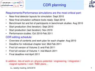
Capstone CDR
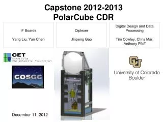
Capstone CDR. Group: AquaLung Mir Minhaz Ali Wilfredo Oteromatos Greg Newcomb Robin Elliott. Presentation Overview. Freddy CCD Parallel Interface CCD Serial Interface Functional Block Diagram Analog to Digital FPGA Connection. Minhaz Hardware Overview Bill of Materials

Capstone CDR
E N D
Presentation Transcript
Capstone CDR • Group: AquaLung • Mir Minhaz Ali • Wilfredo Oteromatos • Greg Newcomb • Robin Elliott
Presentation Overview • Freddy • CCD Parallel Interface • CCD Serial Interface • Functional Block Diagram • Analog to Digital • FPGA Connection • Minhaz • Hardware Overview • Bill of Materials • Fiber and Camera Assembly • CCD and Connection • Greg • USB Interface • Easy USB Chip • Connection • Device Driver to handle USB • Driver to GUI • Robin • Software Functionality • Software Flowchart • AquaImage • Program Launch and Menu • Time Chart • Milestone Tasks
Bill of Materials (BOM) • 1 meter long optical fiber with built in camera • Ti CCD Sensor (TC237B) • Hi speed clock driver for CCD (EL7202C) • Octal buffer for CCD serial driver ( 74ACT240NS) • Spartan 3 FPGA with 1M-byte of Fast Asynchronous • USB Chip (FT245BM) • USB Cable and connector • 8bits ADC(AD7825) • EPROM (93LC46B-I/P) • Clock (12.5 MHz) (CSTLS6M00G53Z-B0) • Crystal Resonator (6MHz) • Variable output voltage regulator (PTN7800) • Other hardware, Capacitor and resistor.
Optical Fiber and Camera • 7000 pieces of fiber inside creating full color image. • 0.5mm diameter glass fiber imaging bundle enables scope to bend around . • Very inexpensive(120$) for 1M long fiber with camera • 2 Xeon light bulbs to illuminate the image. 1M long Optical Fiber Camera Tip Eye Piece
Charge Couple Device (CCD) • 0.34M Pixels Per Field • 658(H) x 469(v) Active Elements • Multimode readout capability • Progressive Scan • Duel Line readout • Image Area line Summing • Low Dark Current • 7.4µm x 7.4µm pixel size • 12.5 MHz Clock
Module 1: CCD • Four Functional Blocks: • Image sensing area • image storage area • serial register gate • low noise signal processing amplifier block • The storage area and serial gate are used to transfer charge line by line from storage area into serial register • After transfer the pixel are clocked out and sensed by charged detection node.
Drivers: EL7202C (non-inverting) Image Area Gate (IAG) Storage Area Gate (SAG) - Input: CLK(12.5MHz) Output: Logic signals to control Image and Storage Areas. Purpose: Activates the Image Area and Opens the Storage Area. Module 2: CCD Parallel interface CCD Driver
Progressive Scan Mode Two register available for high speed data transfer Drives the Serial Register Gate (SRG) 12.5Mhz clk. Signal. 74ACT240 Octal buffer Allows data to be pulled from the serial registers. Input: CLK (12.5MHz) Output: Driving signal. Module 3 : CCD Serial Driver Octal Buffer
Functional Block Diagram Parallel Driver Serial Driver
Analog to Digital Converter • AD 7825 • 2Msps • 420nS conversion time • PWR Dissipation 36mW • Input: 2 AC signals from CCD out1 and 2. • Output: 8 Bits Parallel to FPGA. • Purpose: Conversion from CCD analog output to FPGA A-2 header.
FPGA: Spartan III Inputs: Data from ADC End of Conversion (EOC) signal from ADC. Outputs: 8 bits data to USB interface Control signals to: ADC USB (interface) CCD Function: Data timing issues resolutions and sampling. Module 4 : Spartan III FPGA
Easy USB chip • FIFO Interface between FPGA and USB cable • Bidirectional • Transfer data rate 1M byte/sec • Entire USB protocol handled on-chip • Simple to interface with FPGA • USB 2.0 Compatible • Cheap $$$ • EEPROM optional (93LC46B) • Default setting or program with EEPROM • 6 MHz Timing Chip required (CSTLS6M00GS32-B0) • With 8x clock multiplier, works at 48 MHz
Easy USB - FT245BM Single Chip USB <=> parallel FIFO bi-directional data transfer Clock EEPROM Interface Check TXE# Low Control
Easy USB - FT245BM Single Chip USB <=> parallel FIFO bi-directional data transfer Clock Input 8 pin digital signal from FPGA (D0-D7) EEPROM Interface Write when TXE# Low Control
Easy USB - FT245BM Single Chip USB <=> parallel FIFO bi-directional data transfer Clock Input 8 pin digital signal from FPGA (D0-D7) EEPROM Interface Sending over USB cable Output 2 pin signal to USB Cable (USBDP & USBDM) TXE# is Raised Control
Easy USB - FT245BM Single Chip USB <=> parallel FIFO bi-directional data transfer
Physical Connection to USB pins To PC From FPGA Type A/B USB cable
USB Cable • USB 2.0 (“Full Speed”) • Uses NRZI (Non Return to Zero Invert) encoding • Not our problem!
Device Driver to Handle USB • Provided by FTDI free • Version for Windows XP • Will allow for plug & play
Driver to GUI Handoff Notice Interrupt Open File 1
Driver to GUI Handoff Save 1st picture
Driver to GUI Handoff Notice File 1 is Full Open File 1 Picture 1 saved Close File 1
Driver to GUI Handoff Read Data from File 1 Save next picture
Driver to GUI Handoff Finish Getting Data Close File 1 Save next picture Send image to monitor
Driver to GUI Handoff Open File 2 Get Data Save next picture
Software Functionality Pick Up Event Launch Program Display “Moving” Image Y • Option • Buttons • Zoom • Color Contrast • Pause/Unpause • Auto Save • OpenSaved Image Data? N Pick Up Event Exit Program Display Still Image Or None at all
Software Flow Chart ? Valid Mouse Event ? • Display “Moving” Image • Patient name & ID • Zoom/Contrast toggle • Zoom Level (if zoomed) N ? Determine Event ? • Launch Program • initialize software • look for device driver Y ? Image Update Ready ? Y N Y ? Device Driver Found ? ? Data From Driver ? • Auto Save Image • Name, ID, date, time Y Y ? Moving Image ? • Zoom Toggle • Turn off Color Contrast N • Color Contrast Toggle • Turn off Zoom N Display Driver Error N Unpause the Image Display No Signal Pause Current Image Open Saved Image ? Open Saved Image ? Y ? Determine Event ? • Display Still Image • Patient name & ID • Zoom/Contrast toggle • Zoom Level (if zoomed) ? Valid Mouse Event ? Y N N • Exit Program • Close all files • Exit • Confirm
About AquaImage This is the “About” box seen in all Windows applications.
Program Launch • Screen seen at start-up. • Circled items are customized features.
Menu Bar • Menu features included in AquaImage.
Milestone Tasks • Milestone 1 • GUI Complete • Device Driver Implemented/Not Tested • Prototyping and Modular Testing • Milestone 2 • Static Interface Working • Prototyping and Testing Complete • PCB In House