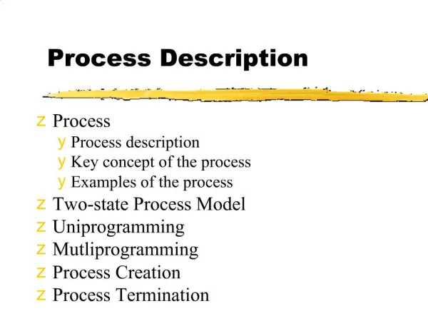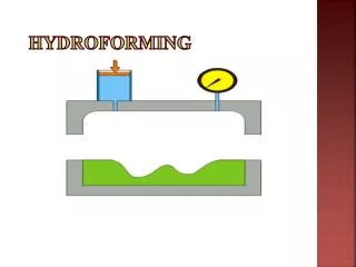
HYDROFORMING PROCESS SHORT DESCRIPTION
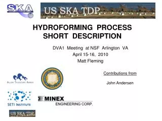
HYDROFORMING PROCESS SHORT DESCRIPTION. DVA1 Meeting at NSF Arlington VA April 15-16, 2010 Matt Fleming. Contributions from John Andersen. A Supply Station B Texture Station ( unsure on this )( not shown ) C Cutting Station D Seam Welding Station E Form Prep Station

HYDROFORMING PROCESS SHORT DESCRIPTION
E N D
Presentation Transcript
HYDROFORMING PROCESS SHORT DESCRIPTION DVA1 Meeting at NSF Arlington VA April 15-16, 2010 Matt Fleming Contributions from John Andersen
A Supply Station B Texture Station ( unsure on this )( not shown ) C Cutting Station D Seam Welding Station E Form Prep Station F Forming Station G Back Assembly Station. ( rim & back ) H Front Assembly Station. Process Stations ( letters ) DVA1, NSF, Arlington, 2010-04-16 Matt Fleming slide 2 of 8
1 Concrete floor foundation. 2 Building or cover ( not shown ) 3 Crane with dual hoists ( maybe 2 cranes ) 4 Coil feed system 5 Cutting machine ( laser plasma or water ) 6 Seam welding machine & table. 7 Welded & prepped reflector blank. 8 Forming mold. 9 Forming pressure back plate. 10 Hold down devices. Stations Tasks ( first ) DVA1, NSF, Arlington, 2010-04-16 Matt Fleming slide 3 of 8
Stations Tasks ( second ) 11 Reflector lift and flip device ( not shown ) 12 Reflector concave up. ( for weld rim ) 13 Backing frame. 14 Backing spars. 15 Other components on back side. 16 Reflector & support lifting tool. ( not shown ) 17 Secondary & other components on front side. DVA1, NSF, Arlington, 2010-04-16 Matt Fleming slide 4 of 8
Mold Proposal Mold would be manufactured in segments surface filled and generated on site. Forming down into a mold supported from a foundation allows better dimensional control and access to surface maintenance DVA1, NSF, Arlington, 2010-04-16 Matt Fleming slide 5 of 8
Mold Proposal Edge shape is very critical and carries very high forces. Edge elements require precision machined steel. DVA1, NSF, Arlington, 2010-04-16 Matt Fleming slide 6 of 8
Mold Parts DVA1, NSF, Arlington, 2010-04-16 Matt Fleming slide 7 of 8
Path to Conclusions Process Analysis Define optics size and shape Define edge shape and edge holding Consult with industrial partners with experience Perform analysis on repeatability ( Ohio State 12m & 15m ) Evaluate results express conclusions for SKA antenna End Production Cost Estimate ( revised ) Redo preliminary cost estimate Secure review and comments from industrial partners. Very preliminary tooling and process costs on next 2 slides DVA1, NSF, Arlington, 2010-04-16 Matt Fleming slide 8 of 8
Process Tasks ( preliminary ) DVA1, NSF, Arlington, 2010-04-16 Matt Fleming slide A
Tooling Cost ( preliminary ) Really big guess See separate slide Costs based on educated guesses DVA1, NSF, Arlington, 2010-04-16 Matt Fleming slide B