Prospects for high-efficiency klystrons
200 likes | 369 Views
Prospects for high-efficiency klystrons . I. Syratchev, CERN. State of art: L-band 10 MW MBK klystrons for ILC. . In terms of achieved efficiency at 10 MW peak RF power level, the existing MBK klystrons provides values very close to the 70%, as is specified in CLIC CDR.

Prospects for high-efficiency klystrons
E N D
Presentation Transcript
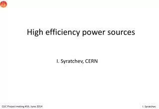
Prospects for high-efficiency klystrons I. Syratchev, CERN
State of art: L-band 10 MW MBK klystrons for ILC. In terms of achieved efficiency at 10 MW peak RF power level, the existing MBK klystrons provides values very close to the 70%, as is specified in CLIC CDR.
Extending technology: L-band 20 MW MBK klystron for CLIC. • We made a study which indicates that the scaling of existing tubes down in frequency may end up in rather powerful (>20 MW) and efficient (>70%) MBK. • Currently we are in process of purchasingsuch a tube(s).
Designing the klystron AJDISK (1-beam klystron optimised by C. Marrelli) 𝜇Perveance = 0.21 Pout ≈ 2.3 MW Efficiency 78. % During optimisation, the tuning of all parameters is done to provide the highest bunched current harmonics at the entrance of the input cavity. The obtained solution is not unique and does not give enough information about the inner structure of the bunch, which also must be optimal in terms change density and electron velocities distributions to get highest efficiency.
Scaling of the klystron parameters Dedicated campaign to make parametric study of the high efficiency klystrons was conducted by Chiara Marrelli (Manchester/CERN) using 1D klystron computer code AJDISK: Perveance indicates how much beam current comes out of the cathode when the voltage V is applied between the cathode and the anode. Perveance can be considered as well as a measure of space charge forces. Lower perveance beam with weaker space-charge forces enables stronger bunching and thus consequently higher efficiency.
Congregated bunch Electron velocities at the output cavity entry For the optimal bunch, the input velocity distribution along the RF phase must be “congregating” – when each consequent electron entering the cavity has higher velocity than preceding one. If then, at the cavity exit all the electrons have equal velocities – the ultimately high efficiency can be obtained. For the given beam power and output cavity impedance this solution is unique.
The first (and only?) ~80% efficient 7-beam MBK built in 1974-6 by S. Lebedinskiy, USSR. Simulations (dash) Measured (solid) Frequency: 0.71 GHz N beams: 7 I total: 2.5 A V beam: 14 kV P out: 27.5 kW Efficiency: 78.6% Pin (nominal) Pin (nominal/2) Congregated bunch
Synthesizing the tube V beam: 490 kV I beam: 270 A RF Power: 105 MW Efficiency: 81% Still 10% of accelerated electrons reduced RF efficiency from 90% to about 80%. To approach efficiency in vicinity of 100%, it is necessary that all the particles, including those who experienced least modulation will reach the core of the bunch.
90% efficient klystron. To achieve this, peripherals should receive much stronger relative phase shift than the core and this could happens only, if the core of the bunch experiences oscillations due to the space charge forces, whilst the peripherals approach the bunch centre monotonously.
Benchmarking with different 1D codes (5 cavities tube) A.Baikov KlypWin Efficiency 86% I. Guzilov KLYS4.5 Efficiency 82.7% Efficiency 87%, with original parameters from A. Baikov. Found reflected electrons. C. Marrelli AJDisk With Increasing the number of disk efficiency also growth – sign of stable solution.
Entrance of the last cavity Exit of the last cavity 78% 80.3%
Recipe#1 for 20 MW. 80% efficient L-band MBK for CLIC Stay at a low micro-perveance. Choose as many beams as you comfortable with: - Reduces the operating voltage (tube length) - Reduces the beam compression (beam dynamics) - Reduces current/beam, weaker magnetic focusing 3. Use all the tricks explained previously K=0.2 K=0.3 K=0.3 K=0.2 Example of the CLIC MBK designed using ‘conventional’ MBK gun technology (8 beams). Simulated by I. Guzilov Bunch core oscillations Collecting outside electrons Tube length 3.0 m; 162kV; 80.3%
BAC method. I. Guzilov In order to intensify the process of the core oscillations, one can use the external forces delivered by additional specially tuned idle cavities– this is the base of BAC method Each oscillation in BAC method is prepared in 3 stages: - first cavity gap – traditional bunching; - second cavity gap - alignment velocity spread of electrons; - third cavity gap – collecting the peripherals. This method of spatial enhancing of the core oscillations frequency allows reducing at least by factor of 2 the length of the interaction space for high efficiency klystrons.
Recipe#2 for 20 MW. 80% efficient L-band MBK for CLIC Stay at a low micro-perveance. Choose as many beams as you comfortable with: - Reduces the operating voltage (tube length) - Reduces the beam compression (beam dynamics) - Reduces current/beam, weaker magnetic focusing 3. Use all the tricks explained previously 4. Employ BAC method to reduce the tube length. K=0.2 K=0.3 K=0.3 K=0.2 Example of the CLIC MBK designed using advanced MBK gun technology (30 beams). Simulated by I. Guzilov Bunch core oscillations Tube length reduced to 1.2 m (2.5 times); 116 kV; 80.3%
The company proposed to build MBK demonstrators/prototypes (at S-band) as the first step towards fabrication full scale CLIC 20 MW MBK with efficiency above 80%.
Tube#1. Technology demonstrator. To be built in 1 year (Low risk approach) KIU-147. 40 beams, S-band, 6 MW, 52 kV, 50% with PPM reversed focusing The PPM reversed focusing drawback: At each reverse of magnetic field there are ~5-7% of beam losses. With two periods, the expected efficiency will be dropped down to ~60 % . At a positive side – klystron will be very light , only 90 kg (0.8 m long). Considering that 60 kV is safe limit for operation at air (discharge long the gun insulator), klystron will be able to deliver up to 8 MW peak RF power. With 40 kW average power, it will be able to operate at 1 kHz and 5 microsecond long pulses. Keep the gun, focusing system and collector Replace the klystron body (the same length). Expected efficiency 74.2% : simulated expected
Tube#1 as an RF power source candidate for TULIP project. • Low voltage 52KV. Compact (less expensive) modulator without oil tank. • Light-weight klystron can be placed directly on the frame and connected to modulator via HV cable. Thus eliminating needs for waveguide distribution system with rotary joints. • The new klystron might be cheaper then conventional ones at the same peak power level and it is way more efficient 60% instead of 45% (on the market).
Tube#2. Efficiency demonstrator. To be built in 2 years. This tube will be an extension of the previous one. It will have doubled core oscillations in BAC method (longer body). The expected design efficiency is 85%. We will also implement the solenoidal focusing coil to keep the efficiency as high as possible. Because of the novelty of our approach and less experience with solenoidal coils, we cannot yet guarantee reaching the ultimate efficiency and suggest that demonstrating of efficiency >75% will be considered a success.
Strategy for high-efficiency high RF power klystron development L-band CW (TLEP, proton linac) >30 beams; <30 kV? ??? years 4 years L-band CLIC 30 beams; 116 kV 2/gun+3years L-band CLIC/Double C. Gun 12 beams; 164 kV 2 years Optionally – gun with controlled electrode (2.5 kV) S-band Demonstrator 40 beams; 52 kV L-band CLIC 6-8 beams; 164 kV Exploring X-band MBK L-band ILC 6 beams; 116 kV 2 years Exists 2 40 6 20
Special thanks to: Igor Guzilov Andrey Baikov Chiara Marrelli