Download
1 / 14
140 likes | 259 Views
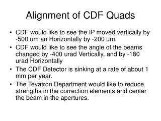
Alignment of CDF Quads. CDF would like to see the IP moved vertically by -500 um an Horizontally by -200 um. CDF would like to see the angle of the beams changed by -400 urad Vertically, and by -180 urad Horizontally The CDF Detector is sinking at a rate of about 1 mm per year.

E N D
Alignment of CDF Quads • CDF would like to see the IP moved vertically by -500 um an Horizontally by -200 um. • CDF would like to see the angle of the beams changed by -400 urad Vertically, and by -180 urad Horizontally • The CDF Detector is sinking at a rate of about 1 mm per year. • The Tevatron Department would like to reduce strengths in the correction elements and center the beam in the apertures.
As founds of the CDF Low Beta Quad elevations The rest of the Tevatron is at 40.6 inches on this plot, or where the outer most elements on this plot are shown.
Slide showing possible Vertical Quad Moves (next slide) • Moves the IP and slope by approximately the desired amount. • Beam trajectory approximately follows the the alignment of the Quadrupoles. • Correction elements between A48 and B11 go to zero current.
Vertical IP moves by -.44 mm Vertical angle changes by -170 urad
Maximum output is .12 mrad Large Vertical Corrections
IP is lowered by 1.1 mm Vert angle change is -50 urad Horizontal IP moves by -.26 mm Horizontal angle changes by -150 urad • Alternative solution with smaller Quad moves • IP move is larger than desired, but angle change is smaller than desired • Correction elements go to zero current between A47 and B14 • Horizontal correction also shown here.
Comparison of Two Vertical Solutions • Large change better matches CDF’s requests • Beam position changes within the Quad apertures are a maximum of 1.9 mm in the small change solution, and a maximum of 3.5 mm in the large change solution. • Correction elements strength go to zero farther out into the arcs in the small change solution. • The beam goes into the Low Beta Quad region lower in the small change solution (position lower in separators). The Quads and Separators are already Low in this region. • As CDF continues to sink, the collision point will move toward the center of the detector if we go with the small change corrections. • We chose the small change solutions because of points 2, 3, and 4.
Horizontal Correction element changes at flattop and at low beta for the chosen Quad moves