Download
1 / 22
220 likes | 386 Views
Stabilization of the FF quads. A.Jeremie B.Bolzon, L.Brunetti, G.Deleglise, N.Geffroy A.Badel, B.Caron, R.Lebreton, J.Lottin Together with colleagues from the CLIC stabilisation WG and CLIC MDI WG. Some comments. Several PhDs: C.Montag (DESY) 1997 S.Redaelli (CERN) 2003

E N D
Stabilization of the FF quads A.Jeremie B.Bolzon, L.Brunetti, G.Deleglise, N.Geffroy A.Badel, B.Caron, R.Lebreton, J.Lottin Together with colleagues from the CLIC stabilisation WG and CLIC MDI WG
Some comments • Several PhDs: • C.Montag (DESY) 1997 • S.Redaelli (CERN) 2003 • B.Bolzon (LAPP) 2007 • M.Warden (Oxford) ~2010 • R. LeBreton (SYMME) ~2012 • Active vibration control is not yet a mature technology. • Activity should be defined as R&D but with CLIC engineering as objective. • It will take time to achieve the final objective but a work plan has been agreed with CDR as an important milestone. • Each time a new team starts this study, there is a non negligible “learning period”. Initially, only vertical direction was studied
What can active stabilisation do? Since the isolation systems don’t isolate 100%, but only reduce the vibrations by a given factor (x10 for common systems, x100 VERY difficult, x1000 “impossible”) • The initial vibration background has to be as low as possible => if we want • MB stab of 1nm, the ground should already be 10nm • 0.15nm for the FF, the support should not be subjected to more than 2nm. • Vibration measurements have shown: • Ground measurements at 1Hz vary from 2nm (LEP) to 150nm (ATF2). • Common detectors move already by 30nm to more than 100nm!
FF support issues • How can it be supported inside the detector? Are we considering a Push-Pull scenario? A study to be done • Cantilever on detector • Cantilever from/on tunnel • Multifeet from detector • Cantilever from ground (height!!!) • Suspended from detector • Suspended from ceiling (correlation possible for both QD0?) • Common girder through detector… • Need an in depth study with detector conception. • A detector can never be built with the right vibration tolerances!
Integration for the Push-Pull 17 m 8.6 m
Longer L* CLIC08 • Study prompted by the CLIC FD stability challenge (< 0.2nm) • Double the L* and place FD on a stable floor • Initial study show that L*=8m optics is possible (CLIC08 workshop) • Some (maybe tolerable) impact on luminosity is still unavoidable (A.Seryi, 2008) But there are drawbacks: R.Tomas et al have shown a ~30% luminosity loss and tuning trickier
FF support issues • How can it be supported inside the detector? Are we considering a Push-Pull scenario? A study to be done • Cantilever on detector • Cantilever from/on tunnel • Multifeet from detector • Cantilever from ground (height!!!) • Suspended from detector • Suspended from ceiling (correlation possible for both QD0?) • Common girder through detector • Need an in depth study with detector conception • A detector can never be built with the right vibration tolerances! • Would the FF magnet be simpler for L*=8m (without the spent beam in the way)? What if we only keep the L*=8m for the first stabilisation studies (or slightly shorter L* with cantilever FF)?
Support Table Support Tube A.Hervé 2009
Introduction Example of spectral analysis of different disturbance sources • Ground motion : • Acoustic disturbance : A pink noise on a large bandwidth Seismic motion Cultural noise • Amplified by the structure itself : the eigenfrequencies • 2 different functions: • Isolate • Compensate the resonances
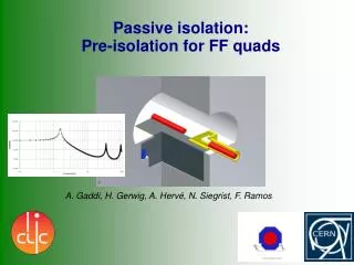
Sub-Nanometer Isolation CLIC small quadrupole stabilised to nanometer level by active damping of natural floor vibration (S.Redaelli 2003) CERN vibration test stand passive active
Resonance compensation Al 2.5 m beam First eigenfrequencies in the same region as the ILC FF SC magnet Cantilever configuration considered for FF support Compensation at end of beam where displacements are big LCWS2007, EPAC2008
Tests possibilities Tests in simulation • A finite element model of the structure : • Dynamics equation : • M : Mass matrix • C : damping matrix • K : stiffness matrix Ex : force (actuator) applied to a point • A prediction of the mechanical structure response • Requires an updating to be as representative as possible to the real setup • Available under Simulink, in the form of a state space model in order to test feedback loops. • The purpose of the simulation : • To adjust the feedback loop • To increase the test possibilities (multiple configurations for sensors, actuators…) • To analyse the behaviour of the entire beam
Active control Different approaches of the problem • The method used to build the controller : A local model of the process A local model of the process A complete model of the process A knowledge of the process at strategic points f0 f1 fi 1 - A knowledge of the structure at strategic points : for lumped disturbances 2 - A local model of the structure : for the disturbances amplified by eigenfrequencies. 3 - A complete model of the structure : for the entire structure
Active control Tests with the large prototype • Results : integrated displacement RMS
Active control The industrial solution • An industrial solution : the TMC table of CERN. • Composed of a passive bloc, placed on 4 active feet (STACIS). • Passive isolation : attenuates all the high frequency disturbances but amplifies the low frequency disturbances (like a resonant filter). • Active isolation : attenuates the disturbance amplified by the passive isolation (low frequencies disturbances).
Active control Tests with the large prototype • Results : integrated displacement RMS (with active table ON) Actuator electronic noise at 50 Hz • No control • With active isolation (TMC table) • With active isolation (TMC table) and active compensation (PZT actuators)
Active control Multi sensors – Multi actuators • The principle : n measurement points (ex : velocity, acceleration...) Distributed sensors Corrector C(s) Distributed actuators n Forces to apply (actuators) • The method : • Develop a complete model M(s) of the structure (using the modelling -finite element) updated as a function of the behaviour of the structure - results in a state space form • Compute a reduced model Mr(s) which is representative of the structure given by the modelling stage. • Build a robust corrector with the reduced model, using the method of the placement of poles and zeros. • Test in simulation, next step: on the prototype.
FF specific • All these “critical” items are studied by limited resources • Follow closely work done in the stabilisation group and MB specific work (module type 4 , isolator…) • MDI-FF review January 2010 => better view of what will be possible for CDR