Download
1 / 22
230 likes | 472 Views
Carbon Capture & Storage A Technical Overview. Rosalind Parke Principal Advisor, RPS Energy Carbon Capture Legal Programme, 16 th June 2008. The Carbon Cycle. Carbon dioxide is a naturally occurring gas under normal atmospheric conditions

E N D
Carbon Capture & StorageA Technical Overview Rosalind Parke Principal Advisor, RPS Energy Carbon Capture Legal Programme, 16th June 2008
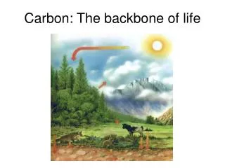
The Carbon Cycle • Carbon dioxide is a naturally occurring gas under normal atmospheric conditions • It is necessary for life and is exchanged, absorbed and emitted via a complex, interwoven series of processes • In the past, the natural processes stabilised CO2 levels in the atmosphere • Human influence has thrown out this balance Respiration,Decomposition & Deforestation Combustion & Industrial Processes Re-vegetation Photosynthesis Diffusion CCS Technical Overview - CCLP June 16 2008
Definition Geological Carbon Capture and Storage is “The active separation and capture of CO2 from the atmospheric emissions of industrial processes and the transport and permanent disposal of the CO2 in deep underground rock formations” • It does not refer to the biological removal and sequestration of CO2 from the atmosphere into natural sinks, such as land use, forestry or oceans CCS Technical Overview - CCLP June 16 2008
“CO2 injection is new, isn’t it?” Not quite…. • Underground injection of natural gas for short-term storage has been in operation for almost 100 years • CO2 Enhanced Oil Recovery (EOR) first applied in Scurry County, Texas in 1972 and has successfully been used throughout the Permian Basin; > 70 active EOR projects • Weyburn EOR project (2000) in Saskatchewan has CO2 piped 204 miles from North Dakota, injecting 1-2MtCO2 pa • GdF’s pilot EGR project at K12B, Netherlands (2004) aims to inject 8MtCO2 over the lifetime of the project • Historically, projects driven by production economics CCS Technical Overview - CCLP June 16 2008
Global View Source: IPCC Special Report, 2005 CCS Technical Overview - CCLP June 16 2008
Storage Projects • Statoil’s Sleipner project in the North Sea (1996) strips the CO2 (~9%) from gas production and injects it at 1MtCO2 pa into a deep saline formation • BP/Sonatrach/Statoil’s In-Salah project in Algeria (2004) similarly strips CO2 and re-injects into the water-filled part of the gas reservoir • StatoilHydro started injection into the Snohvit offshore producing natural gas reservoir in April 2008, goal 0.7 MtCO2 pa • Pilot storage projects also operational at Frio-Texas, Otway Basin- Australia and Nagaoka-Japan CCS Technical Overview - CCLP June 16 2008
So what’s the big deal? • Transition • Existing projects driven by low incremental cost • Future roll-out to heavy industry and power generation requires significant investment, infrastructure development and technical evolution • Purity of CO2 has implications • Scaling up • IEA estimates 6Gt CO2 pa could be captured and stored by 20501 • 6000 Sleipner projects • Implications for resources, co-ordination and delivery • Verification • Lack of monitoring of historic EOR projects provides little quantifiable data on storage and effectiveness Notes: 1. IEA June 2006, Energy Technology Perspectives Scenarios and Strategies CCS Technical Overview - CCLP June 16 2008
Framework for Action Site Identification Capture Transportation Injection & Storage Monitoring Planning and Consents Regulatory/ Policy Framework Market Incentives CCS Technical Overview - CCLP June 16 2008
Framework for Action Site Identification Capture Transportation Injection & Storage Monitoring Planning and Consents Regulatory/ Policy Framework Market Incentives CCS Technical Overview - CCLP June 16 2008
Storage Evaluation • Various geological formations can be utilised - depleted oil and gas reservoirs, coal formations, saline aquifers • Detailed modelling required to assess suitability for storage • Sediment type, porosity, thickness and permeability • Basin location, tectonic activity • Geothermal gradients • Hydrodynamics • Geomechanics and geochemistry • Structural simplicity • Uniformity of cap rock • Prior hydrocarbons production and legacy CCS Technical Overview - CCLP June 16 2008
Framework for Action Site Identification Capture Transportation Injection & Storage Monitoring Planning and Consents Regulatory/ Policy Framework Market Incentives CCS Technical Overview - CCLP June 16 2008
Applied in industrial processes where flue gas streams often >90% CO2; vented In comparison coal-fired power plant10-12% CO2 natural gas combined cycle plants 3-6% CO2 Impurities and total volumes processed reduce effectiveness Compressing CO2 to pipeline pressure represents a large parasitic load (10-30%) However, technology well understood and can be retrofitted Capture Options Post-Combustion Pre-Combustion or Syngas Approach OxyFuel Combustion or Zero Emission • Fuel is gasified to form H2 and CO, which converts to CO2 • CO2 concentrations are high, 15-80% dependent on fuel, and high pressure • Efficient separation, lower incremental energy penalties (<10%) • IGCC technology proven, but costly and new build; not suited to lower rank coals • Combustion takes place in an enriched oxygen environment • Highly concentrated flue gas, >80% CO2 • Incremental energy penalty higher, 8-30% • Current design configuration and materials cannot operate at the higher flame temperature • Flue gas recirculation may mitigate and allow specific retrofit CCS Technical Overview - CCLP June 16 2008
Framework for Action Site Identification Capture Transportation Injection & Storage Monitoring Planning and Consents Regulatory/ Policy Framework Market Incentives CCS Technical Overview - CCLP June 16 2008
Transporting CO2 is an established practice, with over 3000 miles CO2 pipeline in US alone Construction and costs similar to natural gas Distance to storage drives unit costs Principle issue is not R&D, but likely obstacles in siting new networks for increased scale Shipping provides an alternative Similar technology as LPG/LNG transportation; small semi pressurised vessels in operation Relatively new application, requires R&D Investment not purely in ships; liquefaction, intermediate storage and loading/unloading facilities also required; CAPEX&OPEX trade off against pipeline In theory, more attractive over longer distances Transportation CCS Technical Overview - CCLP June 16 2008
Framework for Action Site Identification Capture Transportation Injection & Storage Monitoring Planning and Consents Regulatory/ Policy Framework Market Incentives CCS Technical Overview - CCLP June 16 2008
Injection is targeted below 0.8km since the formation pressure at this depth will maintain the supercritical fluid form In this phase, the CO2 occupies less volume and can diffuse through formation pore spaces like a gas Injection influenced by storage character Injecting cold dense CO2 into lower pressure environments has implications for phase transformation such as solid hydrate formation Temperature differentials are important from the perspective of modelling potential for thermal fracturing of the reservoir Injection Methodology CCS Technical Overview - CCLP June 16 2008
Injection Facilities • A CO2 injection well is similar to a typical gas injection well except that downhole components have higher pressure ratings and corrosion resistance • Acid gas disposal and CO2-EOR have produced significant experience • Production or injection wells in depleted oil/gas fields are often reused as CO2 injection wells, with certain restrictions • Materials such as cement and tubing may require upgrading • Injection zones isolated to desired CO2 target • Additional safety valves installed to mitigate against blowout • Importantly, as fields near depletion and decommissioning, the window for re-utilising existing facilities narrows • The number of wells required depends on many factors, including • Total injection rate • Permeability and thickness of the formation • Maximum injection pressure • Land availability CCS Technical Overview - CCLP June 16 2008
Trapping over Time • Physical traps • Stratigraphic • depositional in nature, trap forms as layering switches permeability e.g. sandstone to shale • primary seal provided by dense overlayer of impermeable cap rock • Structural • tectonic influences bend/fracture rock layers • may be a simple dome, a "crease" in the rocks, or a more complex fault trap • Residual • post-injection, water moves back into the porous formation, increases capillary pressure on CO2 • Geochemical trapping • Solubility • CO2 dissolves in formation water, eliminating buoyancy • Mineral Trapping • Some of the dissolved carbonic acid precipitates out stable carbonates if appropriate mineralogy present in the formation • Ideally, physical and chemical trapping mechanisms interact over time CCS Technical Overview - CCLP June 16 2008
Storage Security • CO2 release scenarios • Ineffective cap rock • Leakage across faults • Leaking injection wells • Abandoned wells • Aquifer flow/diffusion • Thermal fracture Comprehensive initial assessment should model potential risks and identify mitigation strategies CCS Technical Overview - CCLP June 16 2008
Framework for Action Site Identification Capture Transportation Injection & Storage Monitoring Planning and Consents Regulatory/ Policy Framework Market Incentives CCS Technical Overview - CCLP June 16 2008
Monitoring Strategy • Monitoring applies throughout the project lifetime • Prior to injection • Baseline studies are made for future reference against chemical/structural changes • During injection • Repeated 3D-seismic monitoring refines the model of CO2 distribution and inputs to ongoing injection operations (pressure/ well locations) • Well conditions observed for deterioration • Injection rates recorded • Post-injection • Verify CO2 remains contained/ alert to any signs of leakage • There are currently no defined monitoring guidelines either for techniques or timeframes • IEA Weyburn-Midale, Sleipner, Otway, CO2SINK and CO2ReMoVe projects should all provide necessary experience, if disseminated CCS Technical Overview - CCLP June 16 2008
In Summary • Carbon Capture and Storage projects are hugely complex technical projects requiring immense experience across a broad range of skills • R&D is still required to transition this to large scale, multiple source application • Evolution of market and regulatory frameworks will provide the necessary incentives for investment • Timing is critical to exploit current production facilities CCS Technical Overview - CCLP June 16 2008