Download
1 / 46
620 likes | 1.24k Views
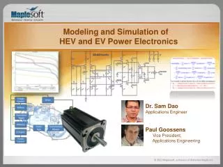
Haus der Technik, München, 2003. Modeling and Simulation for Power Electronics and Electrical Drives. dr. ir. P.J. van Duijsen Simulation Research. Contents. I - Introduction II - Components III - Models IV - Simulation V - Special models VI - Tools VII - Examples VIII - Conclusions.

E N D
Haus der Technik, München, 2003 Modeling and Simulation for Power Electronics and Electrical Drives dr. ir. P.J. van Duijsen Simulation Research
Contents • I - Introduction • II - Components • III - Models • IV - Simulation • V - Special models • VI - Tools • VII - Examples • VIII - Conclusions (c) 2003 Simulation Research
I - Introduction • Identify the components • Models • Parameters (c) 2003 Simulation Research
Identify the components • Different components require different models • First identify these components (c) 2003 Simulation Research
Models • What can we model • Complexity of the model • Availability of parameter (c) 2003 Simulation Research
Parameters • What is a model • Reflection of the users imagination, how a design should work (c) 2003 Simulation Research
II - Components • Power Electronics • Electrical machine • Mechanical load • Main • Control (c) 2003 Simulation Research
III - Models • Multilevel Modeling • Circuit model • Block Diagram • Modeling language (c) 2003 Simulation Research
IV - Simulation • What is simulation • Mathematical methods • Programs (c) 2003 Simulation Research
What is Simulation • Simulation is a prediction of what might happen (c) 2003 Simulation Research
What can we simulate • Large simulations take a lot of time • Large simulations increase complexity and clarity (c) 2003 Simulation Research
Methods and Programs • Mathematical methods • State Space • DAE • MNA • Various programs • Spice • Matlab/Simulink • Saber • Caspoc (c) 2003 Simulation Research
Mathematical Methods • ODE (State Space) • Causal time varying systems • MNA • Circuit models • DAE • Equations • Mathematics (c) 2003 Simulation Research
Various programs • Spice • Electronics (General) • Matlab/Simulink • Systems described by a Block Diagram (General) • Saber • Systems described by equations (General) • Caspoc • Systems and Circuits (PE & ED) (c) 2003 Simulation Research
V - Special models • Power Electronics • Semiconductor models • Heat sink • Parasistics • Analog / digital control • Embedded control • Electrical Machines • Machine models • Mechanical load (c) 2003 Simulation Research
Semiconductor models • Mosfet / IGBT • Gate charge • Cgd non-linear behavior • Temperature dependent On-resistance Rds • Diode • Reverse recovery (c) 2003 Simulation Research
Mosfet / IGBT Dynamics • Non linear gate-drain capacitance Cgd (c) 2003 Simulation Research
Temperature dependence Mosfet • At T=125 Celcius, the drain-source resistance is doubled from Ron to 2*Ron (c) 2003 Simulation Research
Spice diode model • Reverse recovery is modeled by a non-linear capacitor (c) 2003 Simulation Research
Reverse recovery modeling • Model based on measurement (c) 2003 Simulation Research
Reverse recovery • Reverse recovery is dependent on IF and di/dt (c) 2003 Simulation Research
Heat sink models • Parameters from data sheet • Parameters from known structures • Parameters from FEM analysis (c) 2003 Simulation Research
Parameters from a data sheet • Thermal resistance and thermal capacitance are from the manufacturers data sheet • Zth is modeled using parallel RC models • Calculate losses in the mosfet and diode • Calculate temperature and feed back into the semiconductors (c) 2003 Simulation Research
Parameters from know structures • Calculate Rth & Cth from geometry (c) 2003 Simulation Research
Parameters from FEM analysis • Calculate Zth in FEM analysis and use it in the simulation (c) 2003 Simulation Research
Parasitic inductance • Model parasitic inductance for simulating high turn-off voltages Vds (c) 2003 Simulation Research
Analog / Digital control • Analog control as • Electric circuit using Opamp models • Block diagram (more efficient) • Digital control • Logical components • Modeling language (more efficient) (c) 2003 Simulation Research
Block diagram vs Circuit model • Block diagram model for a PI control • 4 blocks • Calculation effort ~ 4 (c) 2003 Simulation Research
Block diagram vs Circuit model • Circuit model for the PI control • No. of nodes = 17 - 4 • Calculation effort ~ (4/3) * (13)^3 (c) 2003 Simulation Research
Using C/Pascal to create models • Replace blocks by C/Pascal code • Model complex control systems • Use the debugger to debug these models (c) 2003 Simulation Research
Embedded Control • Embedded Control models (c) 2003 Simulation Research
Machine models • Connections • Electrical properties • Mechanical properties • Model • State Space equations • Lumped circuit model • Reduced Order Model from FEM analysis (c) 2003 Simulation Research
VI - Tools • Integrated Modeling and Simulation • Modeling Electrical machines • Connection to FEM tools • Modeling Power Electronics • Connection to Packaging analyzers • Modeling Control • Creating Embedded C code • Control design • Small signal modeling • Connection to design tools (c) 2003 Simulation Research
VII - Example • Synchronous generator • PWM induction machine drive • Switched Reluctance Machine • Variable structure system in Caspoc and Simulink (c) 2003 Simulation Research
Example - Synchronous machine (c) 2003 Simulation Research
Example - PWM induction machine drive (c) 2003 Simulation Research
Example - Switched Reluctance machine • Electric connections: • u,I • Mechanical connect.: • T,angular speed (c) 2003 Simulation Research
Example - Variable structure system in Caspoc and Simulink • Caspoc: • Inverter • Machine • Load (c) 2003 Simulation Research
Example - Variable structure system in Caspoc and Simulink • Simulink: • VSS Control • Comparison switched Caspoc model with averaged model in Simulink (c) 2003 Simulation Research
Example Switched Reluctance Machine (SRM) Design of the SRM in Tesla FEM analysis of the SRM in ANSYS Reduced order model from ANSYS in Caspoc Design of the power electronics and control in Caspoc Export of the control algorithm to Embedded C-code for the microprocessor (c) 2003 Simulation Research
Geometric design in Tesla (c) 2003 Simulation Research
FEM analysis in ANSYS (c) 2003 Simulation Research
Complete model and simulation in Caspoc (c) 2003 Simulation Research
Embedded C-code for the control (c) 2003 Simulation Research
Conclusions - SRM • Export of C code from Block diagram • Including the exported code in the simulation • Debugging during simulation (c) 2003 Simulation Research
VIII - Conclusions • A model is a reflection of the users imagination, how a design should work! • Simulation is a prediction of what might happen! (c) 2003 Simulation Research