Download

1 / 31
310 likes | 433 Views
This proposal investigates a Ricean channel model applicable to outdoor environments, specifically for infostations, leveraging 5.1 GHz frequency and measurements from San Francisco's microcell urban landscape. It explores the impact of transmitter-receiver distance on the Ricean K-factor by analyzing low transmitter antenna heights and fixed receiver positions. The study utilizes a modified 2-ray propagation model to predict path losses and evaluate performance under clear line-of-sight conditions. Findings will contribute to optimizing wireless communication designs for outdoor infostations.

E N D
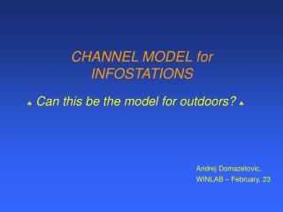
CHANNEL MODEL for INFOSTATIONS Can this be the model for outdoors? Andrej Domazetovic, WINLAB – February, 23
Assuming that the channel is Ricean and using the measurements by Feuerstein, Rappaport et. al. in San Francisco (2-ray model) try to develop the channel model proposal described as the behavior of Ricean K-factor with respect to transmitter-receiver distance. OBJECTIVE
Low transmitter antenna heights (3, 4 and 5m) • Receiver antenna height 1.7m • Clear line of sight path - no shadowing • Carrier frequency 5.1 GHz • Channel bandwidth 100 MHz • Omnidirectional antennas • No mobility (yet) INITIAL ASSUMPTIONS
Brief overview of standard 2-ray propagation model • Brief overview of Propagation over the earth • Closer look into propagation issues • Modified model • Link to Ricean K-factor • Real antenna pattern • Conclusions/Questions OUTLINE
Friis free space equation: Relation between power and electric field: Standard 2-ray propagation model Where: EIRP - effective isotropic radiated power, E - magnitude of radiating portion of electric field in the far field, Rfs - free space intrinsic impedance and Ae - antenna effective aperture Source: [] Rappaport - Wireless Communications
The electric field at receiver: Standard 2-ray propagation model assuming: large distance from the transmitter, Taylor series approximations, perfect ground reflection... Source: [] Rappaport - Wireless Communications
In measurements performed in San Francisco, it was shown that 2-ray model is fairly good model for microcellular urban environment It was also shown that the path loss within first Fresnel zone clearance is purely due to spherical spreading of the wave front: decreases as d-2 and not d-4 (10m being the minimum T-R distance) Standard 2-ray propagation model Source: [] Feuerstein, Rappaport et. al. - Path loss, Delay spread and Outage models as Functions of Antenna Height for Microcellular System Design - TVEH, Aug, 1994
Standard 2-ray propagation model Source: [] Feuerstein, Rappaport et. al. - Path loss, Delay spread and Outage models as Functions of Antenna Height for Microcellular System Design - TVEH, Aug, 1994
Fresnel zone clearance Standard 2-ray propagation model Source: [] Feuerstein, Rappaport et. al. - Path loss, Delay spread and Outage models as Functions of Antenna Height for Microcellular System Design - TVEH, Aug, 1994
Propagation over smooth, conducting, flat earth Bullington: Where: first term - direct wave second term - reflected wave third term - surface wave rest - induction field and ground secondary effects - phase difference between reflected and direct paths Propagation over a plane earth Source: [] W.C. Jakes - Microwave Mobile Communications
Friis free space equation: • The formula is a valid predictor for Prfor d which are in the far-field of the transmitting antenna - Fraunhofer region i.e. when inductive and electrostatic fields become negligible and only radiation field remains • df=2D2/ , df>>D and df>> • For fc = 5.1GHz and the antenna size D = 10cm • df=33.9cm , df>>10cm and df>>5.9cm • If D (largest linear dimension of antenna) and fc increase, so does df - attention must be paid ASSUMTIONS Source: [] Rappaport - Wireless Communications
First Fresnel zone distance: Antenna height: fd: for fc=5.1GHz 3m 70.47m Mobile height:1.7m 4m 118.29m 5m 179.6m ASSUMTIONS Since wavelength=5.9cm, the Bullington equation also holds (surface wave can be neglected) Source: [] Feuerstein, Rappaport et. al. - Path loss, Delay spread and Outage models as Functions of Antenna Height for Microcellular System Design - TVEH, Aug, 1994 [] W.C. Jakes - Microwave Mobile Communications
Ricean K-factor Source: [] Rappaport - Wireless Communications [] Steele - Mobile Radio Communications
Propagation Mechanisms Source: [] Rappaport - Wireless Communications
Reflection coefficient (Fresnel) depends on material properties, frequency, incident angle… It is often related to relative permittivity value: (for lossy dielectric) - some energy absorbed Type of surface (S/m) Poor ground 0.001 4 Average ground 0.005 15 Good ground 0.02 25 Sea water 5 81 Fresh water 0.01 81 Brick 0.01 4.44 Limestone 0.028 7.51 Glass at 10 GHz 0.005 4 If material is good conductor (f</r0) - not sensitive to f For lossy dielectrics: - 0, r - const. with f but may be sensitive Propagation Mechanisms Source: [] Rappaport - Wireless Communications [] W.C. Jakes - Microwave Mobile Communications
From Maxwell’s equations and Snell’s Law: Propagation Mechanisms When the first medium is free space and Source: [] Rappaport - Wireless Communications
Assuming 100MHz bandwidth 200Msamples/second 1.5m path distance in order to detect another path wave Close scatters – practical issue
Some hints that look promising Source: [] IEEE Communication magazine, Jan 2001.
What do you think IMW or JFAI? • What to pursuit? • - If this idea holds, how to prove it? • - If not, should COSTs/ITUs/etc. be investigated better and picked one of those models? • If the channel is really that good why OFDM? • - Simplicity for Downlink (no PAPR headache, implementable on Winlab hardware) • - DS-CDMA (no near-far, fully orthogonal code set, multiple access…) Conclusions/Questions