Download

1 / 50
500 likes | 517 Views
This course covers the laws and theorems of Boolean algebra, simplification of logic expressions, use of K-maps, and design using NAND or NOR gates.

E N D
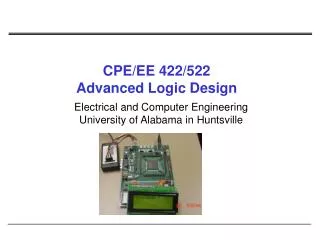
CPE/EE 422/522Advanced Logic DesignL02 Electrical and Computer EngineeringUniversity of Alabama in Huntsville
Outline • What we know • Laws and Theorems of Boolean Algebra • Simplification of Logic Expressions • Using Laws and Theorems of Boolean Algebra or Using K-maps • Design Using only NAND or only NOR gates • Tri-state buffers • Basic Combinational Building Blocks • Multiplexers, Decoders, Encoders, ... • What we do not know • Hazards in Combinational Networks • How to implement functions using ROMs, PLAs, and PALs • Sequential Networks (if time) UAH-CPE/EE 422/522 AM
Review:Combinational-Circuit Building Blocks • Multiplexers • Decoders • Encoders • Code Converters • Comparators • Adders/Subtractors • Multipliers • Shifters UAH-CPE/EE 422/522 AM
Multiplexers: 2-to-1 Multiplexer • Have number of data inputs, one or more select inputs, and one output • It passes the signal value on one of data inputs to the output w s 0 w 0 0 f s f w 1 1 w 1 (a) Graphical symbol (c) Sum-of-products circuit f s w 0 0 w 1 1 (b) Truth table UAH-CPE/EE 422/522 AM
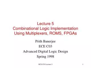
Review:Synthesis of Logic Functions Using Muxes w w w f 1 2 3 w w f 1 2 0 0 0 0 0 0 0 0 0 1 0 w 0 1 3 0 1 0 0 w 1 0 3 w 0 1 1 1 2 1 1 1 w 1 1 0 0 0 0 1 0 1 1 w 3 1 1 0 1 f 1 1 1 1 1 (a) Modified truth table (b) Circuit UAH-CPE/EE 422/522 AM
Decoders: n-to-2n Decoder • Decode encoded information: n inputs, 2n outputs • If En = 1, only one output is asserted at a time • One-hot encoded output • m-bit binary code where exactly one bit is set to 1 w y 0 0 n n 2 inputs w outputs n – 1 y n Enable 2 – 1 En UAH-CPE/EE 422/522 AM
Decoders: 2-to-4 Decoder w w y y y y En 1 0 0 1 2 3 w 0 0 0 0 1 0 0 1 y 0 0 1 0 1 0 0 1 w 1 1 1 0 0 0 1 0 1 1 1 0 0 0 1 y x x 0 0 0 0 0 1 (a) Truth table y 2 w y 0 0 w y y 1 1 3 y 2 En y En 3 (c) Logic circuit (b) Graphic symbol UAH-CPE/EE 422/522 AM
Encoders • Opposite of decoders • Encode given information into a more compact form • Binary encoders • 2n inputs into n-bit code • Exactly one of the input signals should have a value of 1,and outputs present the binary number that identifies which input is equal to 1 • Use: reduce the number of bits (transmitting and storing information) w 0 y 0 n n 2 outputs inputs y n – 1 w n 2 – 1 UAH-CPE/EE 422/522 AM
Encoders: 4-to-2 Encoder w w w w y y 3 2 1 0 1 0 w 0 0 0 0 1 0 0 w 1 y 0 0 1 0 0 1 0 0 1 0 0 1 0 w 2 1 0 0 1 1 0 y 1 w 3 (a) Truth table (b) Circuit UAH-CPE/EE 422/522 AM
Encoders: Priority Encoders • Each input has a priority level associated with it • The encoder outputs indicate the active inputthat has the highest priority (a) Truth table for a 4-to-2 priority encoder w w w w y y z 3 2 1 0 1 0 0 0 0 0 d d 0 0 0 0 1 0 0 1 x 0 0 1 0 1 1 x x 0 1 1 0 1 x x x 1 1 1 1 UAH-CPE/EE 422/522 AM
Code Converters • Convert from one type of input encoding to a different output encoding • E. g., BCD-to-7-segment decoder c e g w w w w a b d f 3 2 1 0 a a 0 0 0 0 1 1 1 1 1 1 0 b w 0 0 0 1 0 1 1 0 0 0 0 0 f b c w 0 0 1 0 1 1 0 1 1 0 1 1 d w 0 0 1 1 1 1 1 1 0 0 1 g 2 e e c w 0 1 0 0 0 1 1 0 0 1 1 3 f 0 1 0 1 1 0 1 1 0 1 1 g d 0 1 1 0 1 0 1 1 1 1 1 (b) 7-segment display 1 1 1 0 1 1 1 0 0 0 0 (a) Code converter 1 1 1 1 1 1 1 1 0 0 0 1 0 0 1 1 1 1 1 0 1 1 (c) Truth table UAH-CPE/EE 422/522 AM
Hazards in Combinational Networks • What are hazards in CM? • Unwanted switching transients at the output (glitches) • Example • ABC = 111, B changes to 0 • Assume each gate has propagation delay of 10ns UAH-CPE/EE 422/522 AM
Hazards in Combinational Networks • Occur when different paths from input to output have different propagation delays • Static 1-hazard • a network output momentarily go to the 0 when it should remain a constant 1 • Static 0-hazard • a network output momentarily go to the 1 when it should remain a constant 0 • Dynamic hazard • if an output change three or more times, when the output is supposed to change from 0 to 1 (1 to 0) UAH-CPE/EE 422/522 AM
AB 01 10 00 11 C 1 1 1 1 1 1 1 0 1 Hazards in Combinational Circuits AB 01 10 00 11 C 1 0 1 To avoid hazards: every par of adjacent 1s should be covered by a 1-term UAH-CPE/EE 422/522 AM
Hazards in Combinational Circuits Why do we care about hazards? • Combinational networks • don’t care – the network will function correctly • Synchronous sequential networks • don’t care - the input signals must be stable within setup and hold time of flip-flops • Asynchronous sequential networks • hazards can cause the network to enter an incorrect state • circuitry that generates the next-state variables must be hazard-free • Power consumption is proportional to the number of transitions UAH-CPE/EE 422/522 AM
Programmable Logic Devices • Read Only Memories (ROMs) • Programmable Logic Arrays (PLAs) • Programmable Array Logic Devices (PALs) UAH-CPE/EE 422/522 AM
Read-Only Memories • Store binary data • data can be read out whenever desired • cannot be changed under normal operating conditions • n input lines, m output lines => array of 2n m-bit words • Input lines serve as an address to select one of 2n words • Use ROM to implement logic functions? • n variables, m functions UAH-CPE/EE 422/522 AM
Basic ROM Structure UAH-CPE/EE 422/522 AM
ROM Types • Mask-programmable ROM • Data is permanently stored (include or omit the switching elements) • Economically feasible for a large quantity • EPROM (Erasable Programmable ROM) • Use special charge-storage mechanism to enable or disable the switching elements in the memory array • PROM programmer is used to provide appropriate voltage pulses to store electronic charges • Data is permanent until erased using an ultraviolet light • EEPROM – Electrically Erasable PROM • erasure is accomplished using electrical pulses (can be reprogrammed typically 100 to 1000 times) • Flash memories - similar to EEPROM except they use a different charge-storage mechanism • usually have built-in programming and erase capability, so the data can be written to the flash memory while it is in place, without the need for a separate programmer UAH-CPE/EE 422/522 AM
Programmable Logic Arrays (PLAs) • Perform the same function as a ROM • n inputs and m outputs – m functions of n variables • AND array – realizes product terms of the input variables • OR array – ORs together the product terms UAH-CPE/EE 422/522 AM
PLA: 3 inputs, 5 p.t., 4 outputs UAH-CPE/EE 422/522 AM
nMOS NOR Gate UAH-CPE/EE 422/522 AM
AND-OR Array Equivalent UAH-CPE/EE 422/522 AM
Modified Truth Table for PLA • 0 – variable is complemented • 1 – variable is not complemented • - – not present in the term UAH-CPE/EE 422/522 AM
Using PLA: An Example Eight different product terms are required!? For PLA we want to minimize the total number of product terms, not the number of product terms for each function separately! UAH-CPE/EE 422/522 AM
1 1 1 1 1 1 1 1 1 1 1 1 1 1 1 1 1 1 1 1 1 1 1 1 Using PLA: An Example ab ab ab 01 10 00 11 01 10 00 11 01 10 00 11 cd cd cd 1 00 1 00 00 01 01 01 11 11 11 10 10 10 F1 F2 F3 UAH-CPE/EE 422/522 AM
Using PLA: An Example UAH-CPE/EE 422/522 AM
Programmable Array Logic (PALs) • PAL is a special case of PLA • AND array is programmable and OR array is fixed • PAL is • less expensive • easier to program UAH-CPE/EE 422/522 AM
Programmable Array Logic (PALs) Unprogrammed Programmed UAH-CPE/EE 422/522 AM
PALs • Typical PALs have • from 10 to 20 inputs • from 2 to 10 outputs • from 2 to 8 AND gates driving each OR gate • often include D flip-flops UAH-CPE/EE 422/522 AM
Logic Diagram for 16R4 PAL UAH-CPE/EE 422/522 AM
Logic Diagram for 16R4 PAL UAH-CPE/EE 422/522 AM
Using PALs: An Example x x x 1 2 3 Implement the following: P 1 P 2 P 3 P 4 AND plane UAH-CPE/EE 422/522 AM
Using PALs: An Example x x x 1 2 3 P 1 f 1 P 2 P 3 f 2 P 4 AND plane UAH-CPE/EE 422/522 AM
Select Enable f 1 Flip-flop D Q Clock To AND plane Typical PALs • Typical PALs have • from 10 to 20 inputs • from 2 to 10 outputs • from 2 to 8 AND gates driving each OR gate • often include D flip-flops MUX output is “fed back” to the AND plane. Why? UAH-CPE/EE 422/522 AM
To Do • Read • Textbook chapters 1.5, 3.1, 3.2, 3.3 UAH-CPE/EE 422/522 AM
Sequential Networks • Have memory (state) • Present state depends not only on the current input, but also on all previous inputs (history) • Future state depends on the current input and state X = x1 x2... xn Q = Q1 Q2... Qk Z = z1 z2... zm x1 z1 x2 z2 Q Flip-flops are commonly used as storage devices:D-FF, JK-FF, T-FF xn zm UAH-CPE/EE 422/522 AM
Clocked D Flip-Flop with Rising-edge Trigger Next state The next state in response to the rising edge of the clock is equal to the D input before the rising edge UAH-CPE/EE 422/522 AM
Clocked JK Flip-Flop Next state JK = 00 => no state change occurs JK = 10 => the flip-flop is set to 1, independent of the current state JK = 01 => the flip-flop is always reset to 0 JK = 11 => the flip-flop changes the state Q+ = Q’ UAH-CPE/EE 422/522 AM
Clocked JK Flip-Flop Next state T = 1 => the flip-flop changes the state Q+ = Q’ T = 0 => no state change UAH-CPE/EE 422/522 AM
S-R Latch UAH-CPE/EE 422/522 AM
Transparent D Latch UAH-CPE/EE 422/522 AM
Transparent D Latch UAH-CPE/EE 422/522 AM
Mealy Sequential Networks General model of Mealy Sequential Network (1) X inputs are changed to a new value • After a delay, the Z outputs and next state appear at the output of CM (3) The next state is clocked into the state register and the state changes UAH-CPE/EE 422/522 AM
x z Q An Example: 8421 BCD to Excess3 BCD Code Converter UAH-CPE/EE 422/522 AM
State Graph and Table for Code Converter UAH-CPE/EE 422/522 AM
State Assignment Rules UAH-CPE/EE 422/522 AM
Transition Table UAH-CPE/EE 422/522 AM
K-maps UAH-CPE/EE 422/522 AM
Realization UAH-CPE/EE 422/522 AM